Print quality instructions and additional documentation are available from my store and Rebrickable
Click on pictures to
enlarge
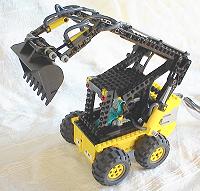
 The Lego LS160 |
ConceptThe skid steer concept was introduced by Bobcat in 1960, in response to demands for a loader that would be able to manoeuver effectively in confined spaces. The method of steering and propulsion is conceptually similar to that of a tracked vehicle - the two wheels on the same side move in unison, with each pair on opposite sides capable of being driven independently. If both pairs are driven forward with the same speed, then the loader moves forward, but if they are driven in opposite directions, the loader will turn on itself. This flexibility allows incredibly compact manoeuvers to be effected, and skid steer loaders are now found in a wide variety of applications including construction, agriculture and industry. The clever aspect of the concept lies in the distribution of weight in the vehicle. When unladen, the centre of gravity lies towards the rear of the vehicle near the engine, which makes the centre of steering occur right in the middle of the rear axle, with the front wheels skidding around this. If the loader has significant weight in the bucket, the centre of gravity moves to the front of the vehicle making the rear wheels skid around the front axle. While useful in this regard, the offset distribution of weight can sometimes lead to instability, particularly when travelling up and down inclines and suddenly changing direction from reverse to forward. Counterweights are sometimes employed to help reduce this effect. |
|
|
|
|
|
|
|
|
Click on pictures to
enlarge |
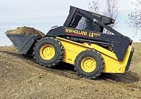
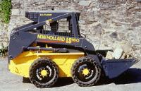
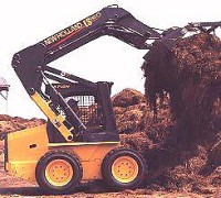
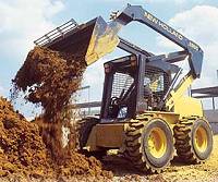
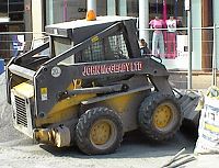
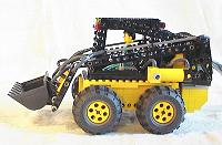
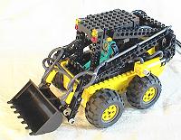
InspirationThis year in Glasgow, the pedestrianised shopping areas in Buchanan street and Argyll street were having their stonework redone, a fairly large project taking some time to complete. While this was going on I noticed a slightly larger version of the vehicle pictured opposite, a New Holland LS160, being used for what seemed to be general fetching and carrying duties. I thought it was a great looking vehicle, and would be excellent as the basis for my first model with the Lego pneumatic elements. Also under consideration were the Bobcat loaders, but the yellow and black colour scheme of the LS160 seemed far more keeping with the construction aesthetic. |
|
|
|
Click on pictures to enlarge |
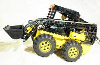
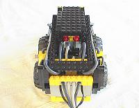
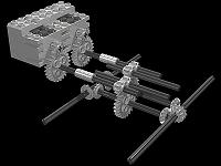
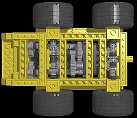
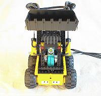
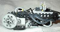
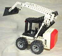
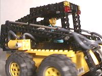
PropulsionThe real LS160 is powered by a 42hp diesel engine giving a nippy maximum speed of 7.7 mph, with power provided to each pair of wheels by hydrostatic motors. The operator controls the speed and direction of the vehicle with two joysticks, each one linked to a pair of wheels on each side, in a similar fashion to that found in tracked vehicles. Moving both joysticks forward will drive the vehicle forward; both back will move the vehicle backwards; one forward and the other back will make the vehicle turn on itself. Of course, those are just extremes and movements in between those are also possible. Hydrostatic motors are not (yet) available within the Lego builder's repertoire, so I decided to simulate this using two independently controlled electric motors, one driving each side of the vehicle. Powering the Lego LS160 in this way actually prove to be quite a challenge. As mentioned before, distribution of weight is important for the loader to steer properly, which also turned out to be the case for the Lego model. Simple mockups with the centre of gravity near the middle resulted in a great deal of judder and poor steering control. I concluded that the easiest way to solve this problem would be to follow the real LS160 example and situate both motors at the rear of the vehicle. This, however, prove to be more difficult than I initially thought. The scale of the model is based roughly around the size of the Technic figures, and more accurately on the size of the balloon tyres, which led to some fairly severe size constraints. For example, the body of the vehicle had to be 8 studs wide, meaning that the motors would occupy the entire width if they were mounted side by side, and that the drive trains at chassis level had to fit into a width of 6 studs. Since skid steering puts considerable stress on the components, the entire structure had to be fully braced to prevent it tearing itself apart, particularly around the small bevel gears. As can be seen from the picture opposite, the solution is quite simple, yet it took a significant amount of trial and error to get there. |
|
|
|
|
|
|
|
|
|
Click on pictures to enlarge |
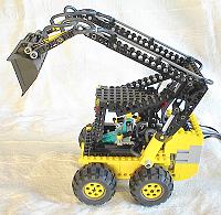
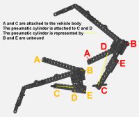
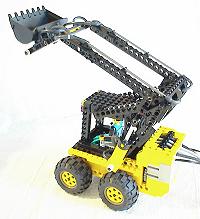
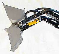
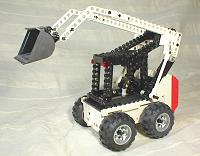
Boom LinkageTraditional loaders usually have a boom with a bucket at one end and the rotation point at the other, making the lift path of the bucket follow an arc when raised and lowered. The result of this is that the bucket is closer to the loader when at its lowest and highest points, and furthest away at the midpoint. This is not always desirable; for example, if loading a dump truck or palettes, it is preferable that the bucket is furthest away from the loader at the highest lift point, allowing more accurate positioning and quicker working. One solution to this is to employ a four bar linkage such as the Superboom system on the LS160 which gives a vertical lift path. The path is not strictly vertical, however, as it gradually moves the bucket forward as it is raised, as mentioned above. Recreating this linkage in Lego was fairly tricky as the getting the length and rotation point of each beam in the linkage correct was crucial; any slight inaccuracies severely affected the lift envelope and path. The most difficult bit was finding a good position for the pneumatic cylinders, as they have a much shorter stroke (in scale terms) than the hydraulic rams on the LS160. The vertical lift effect of the linkage can be seen on the "ghosted boom" picture opposite and in the video above. |
|
|
|
|
|
|
|
|
|
|
|
|
Click on pictures to enlarge |
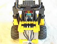
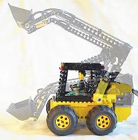
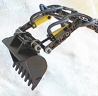
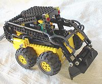
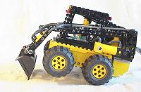
BucketWhile a bucket is usually found on the end of a loader boom, a variety of alternative attachments can be employed for various applications. Examples of those include fork lift devices, pneumatic drills and backhoe diggers. I decided to go for the generic case of the bucket, particularly since I had one of just about the right size handy. The most appropriate pneumatic cylinders, in terms of scale, for moving the bucket were two of the smaller ones linked in parallel. By linking them in parallel, I hope to gain three things - realism to the real LS160, more power, and slower motion, the latter to improve controllability. In the end it was just as well that I used two, as these small pneumatic cylinders are weak compared with the larger ones. Compressed air was provided to the cylinders from the base to the top of the boom via a pair of "flex system" pipes, with hoses attached at each end where movement occurs. As well as being more in keeping with real hydraulic devices, this adds a pleasing aesthetic touch to the model. The spaghetti effect near the bucket is caused by the necessity of splitting the two pipes in order to drive the cylinders in parallel. The Lego bucket actually has two sets of holes for attaching to the boom and the actuating element, but I found that placing the end of the pneumatic cylinder in the latter did not provide a large enough range of movement. The cylinders were therefore attached below this point, giving the desired movement but at the expense of making their effect less powerful. Nonetheless, the bucket power was still quite effective, easily lifting the vehicle onto its rear wheels by itself. |
|
|
|
|
|
|
|
|
|
|
|
Click on pictures to enlarge |
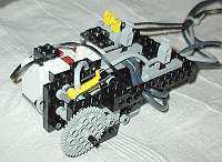
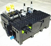
Control UnitThe control unit provides a way for the user to exercise all the features of the LS160 remotely by means of an umbilical carrying compressed air and electrical power to the vehicle. While the unit may look unwieldy, some degree of ergonomic design has been incorporated. The yellow levers are responsible for controlling the vehicle movement in the manner described in the propulsion section, while the grey levers control the flow of compressed air to the boom and bucket. Both compressor and a 9V battery unit are integrated with the control unit - the batteries are used to power the two motors on the LS160, as well as a third motor responsible for driving the compressor. The compressor is based on a design by Michael Powell, although some modifications have been made, most notably the replacement of the belt drive system by gears, which I found to be more efficient. The use of gears was made possible by the incorporation of a pressure cut off switch, which turns the compressor motor off when the pressure in the pneumatic system exceeds a certain level. When the pressure drops below that level, the motor is started up again automatically, providing compressed air for boom and bucket operation on demand. Surprisingly, adding all this extra functionality to the compressor does not significantly increase its size. So went the description of the original controller, however since then I have designed the improved version shown to the left. This one is more economical in terms of battery consumption and cost of Lego pieces used as well as being more user friendly. There is a detailed description and a DAT file available for this controller on the ideas page. |
|
|
|
|
|
|
Click on pictures to enlarge |
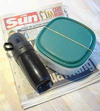
ConclusionsWhen setting out to create a model of this type one usually has certain goals in mind, some of which can be achieved and some which go by the wayside during the actual building process. While my main priorities in this case were the achievement of mechanical and aesthetic accuracy to the original LS160, of almost equal importance was making the model scale well with Technic figures, although I was prepared to let this slip a little for the sake of the first two. On the whole I am very happy with this model - in terms of dynamics, the way the model looks, feels and moves is very similar to the real thing, so much so that a friend who is familiar with skid steer loaders was able to do make it wheelie when suddenly changing from reverse to forward, a feature of the real thing I was previously unaware of! The model has proven exceptionally robust as a result of the meticulous structural bracing, resulting in a drive train which can exert a surprising amount of torque. The drive train gears never grind, even if you physically stop the wheels moving, and no section of the vehicle has come apart in its lifetime. As for appearance, I think the essence of the original has been captured well - certainly the model is instantly recognisable as a skid steer loader. The vertical lift boom linkage is something I find particularly pleasing, as the movements within it seem very cunning and elegant to those who are mechanically minded. My only real criticism is that to make the model work I had to increase the scale slightly, so that it is a little on the large side for a Technic figure. Still, I don't think he looks particularly out of place in the model - it is only when you have stood next to the real thing that you realise the model is just a little bit on the large side. Above all, this model is great fun - everyone wants to set up wee games and challenges when they play with it, including mercy dashes of coins to a mug and shoveling snow from a defrosting freezer to a basin. It's going to be a tough one to break up! |
|
|
|
|
|
|
|
|
|
|
|
|
|
|
References
|