
Click on pictures to
enlarge |
IntroductionSkips (or dumpsters if you happen to live in the US) are very much a facet of modern society - where there is waste you will find them. Much maligned yet incredibly useful, they are an essential part of many construction and demolition projects. While I have no idea of when they first came about, I imagine it would have been almost immediately after the invention of the wheel. The type shown in this web page probably developed from the desire to have a large container with tipper functionality constantly available on site without the truck itself having to be present. This is particularly relevant when the loading process is slow, freeing up the truck for other jobs in the meantime. As with most modern construction equipment, skips come in many different types, usually defined by the weight and volume of material they can carry. The most common type of skips seen in the UK are small light duty ones, shaped a bit like parallelograms, which can carry up to 16 cubic metres of material. The trucks used to transport those load and unload the skips with chains attached to hydraulically powered davits. For heavy duty use such as demolition and construction site carry off, the larger variant of skip seen on this page is more often employed, with capacities of up to 50 cubic metres. The method used by the trucks to load and unload the skips in this case are generally known as "hook lift" systems, which also allow the skip to be tipped from the truck chassis in the same way as a standard tipper truck. Sometimes they are also known as roll on/roll off skip systems, or "roro" for short. |
|
|
|
Click on pictures to
enlarge |
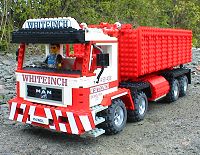
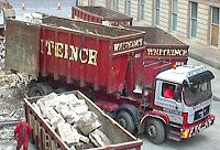
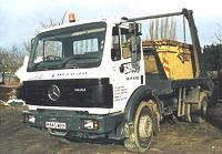
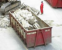
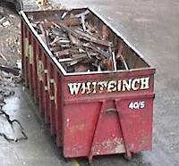
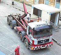
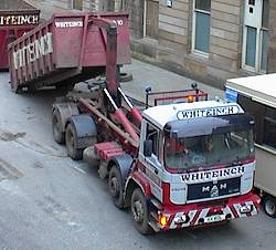
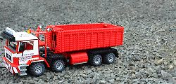
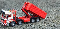
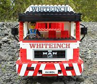
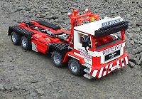
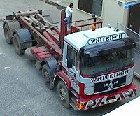
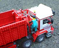
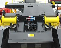
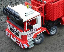
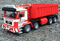
InspirationI have wanted to build the ultimate Lego skip truck for quite literally decades! Around 1975, my parents gave me Lego set number 612 as a present, which could best be described as a hybrid skip/tipper truck. It was great at the time, but the fact that the container would always fall off was rather annoying! Fast forward to the year 2000 and Whiteinch Demolition of Glasgow were demolishing a building across the road from my flat, which was a good opportunity to gather photos of construction machinery for Lego model inspiration. One vehicle which caught my eye in particular was a heavy duty skip truck of one of my favourite types, a four axled MAN in very distinctive livery, ideal for capturing in Lego if I could only figure out the workings... Research showed that the truck chassis and hook lift system on skip trucks of this type are generally acquired from separate suppliers and put together afterwards, although there are standards to ensure a proper fit. A well known manufacturer of hook lift systems in the UK is Edbro, who kindly sent me detailed information on their Rolatip "Hook Lift Demount Body System" which prove invaluable as a blueprint to base the model on. The actual truck was a MAN model 32.322, which is not part of their current product range and as a result it prove difficult to get adequate information on it; however, there is a more recent equivalent to this truck in the current MAN F2000 Evolution range, the 35.364VF on which I was able to download enough information for modelmaking purposes. Strictly speaking the model is therefore a bit of a hybrid, although when you get down to 1:20 scale in Lego terms there is not really that much difference between them. I had also just received a prototype eight channel radio control unit custom designed by John Barnes for integration into the Lego system, which I thought would be ideal for this truck. I thought that total remote control of all the truck's functions, especially skip loading and unloading, would be something really special. As a final note, the colours on the Whiteinch vehicle are actually maroon and very light grey; the former is not available in Lego at all and the latter only sparingly, so I made the decision to use red and white. Given that the photos of the real truck are a little overexposed, it doesn't really matter that much at all :-) |
|
|
|
|
|
|
Click on pictures to
enlarge |
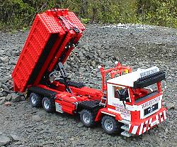
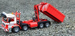
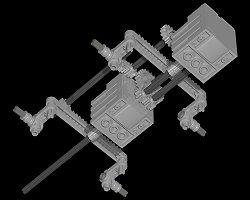
TippingTo start with, I will describe the most obvious function of this vehicle, that of tipping the skip. There have been a few official Lego Technic models of tipper trucks before; the first that sprung to mind was the alternative model for the 855 Mobile Crane, which I built many years ago, and the second was the 8848 tipper which also had a digger bucket at the front, which I have never actually seen other than the instructions on Brickshelf. The biggest influence I obtained from both of those was the use of a rack and pinion system for raising and lowering the skip, although the version I used is more like the one used in the 855 Mobile Crane itself rather than the tipper truck alternative. A big problem with using horizontal rack and pinion systems of this type is that the mechanical advantage generated by the linkage varies as the skip is tipped. The greatest amount of force required is when the skip is horizontal and you wish to tip it up, which is precisely where the mechanical advantage of the rack and pinion is at its worse. While this does not necessarily prohibit one from using this system, it must be realised that a great amount of stress is placed on the components involved, meaning that strength of construction and a lot of gear reduction is paramount. The rack and pinion system in this model was also required to double as a skip loading mechanism, which made the design significantly more difficult. While tipping, the lifting mechanism acts like a scissor lift platform - this can be seen in the pictures to the left. Using this method a maximum tip angle of 45 degrees was obtained, which I was very happy with; in general real tippers can reach 50 degrees, but getting a mechanism which could tip to nearly this and also load skips was somewhat of a challenge. The door at the back of the real skip opens to one side, however, I really wanted a door like that on traditional tippers which swings along the top of the skip, so I designed it this way with a very simple locking mechanism which works quite well in practice. It takes just under a minute to tip the skip fully, which may seem slow in Lego terms but is actually about three times faster than the real truck; |
|
|
|
|
|
|
|
Click on pictures to
enlarge |
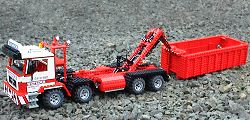
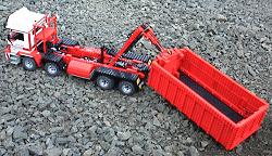
Skip LoadingBeing able to tip the skip is one thing, but unloading and loading it without human assistance is far more complex, the latter particularly so. When building the model I realised that this is to do with the concept of entropy, which states that it is easier to go from an ordered state to a disordered state than vice-versa. This relates to the truck and skip system in that there is more order when the skip is mounted on the truck than when the two are separate, so it is easier to remove the skip than put it back on again. In a nutshell, It's the difference between a tidy and a messy room. Anyway, enough physics and more mechanics. The same rack system that provides the tipping motion is used to move the hook through an angle of up to 155 degrees instead of 45 degrees by locking the lower half of the boom to the chassis and allowing it to pivot in the middle. This range of movement is enough to move the skip from the loaded state to the ground behind the truck, with rails on both the truck and skip ensuring the two stay parallel to each other. Of course, by increasing the range of movement of the boom the mechanical advantage of the rack system is reduced correspondingly so approximately 3.5 (155/45) times the effort is required from the motor. Where does the aforementioned entropy come in? When loaded, one aspect of order is the orientation of the skip and truck which are parallel relative to each other. When loading, it is almost certain that the skip and truck will be at an angle to each other, therefore this angle must be removed during the loading process so that the skip and truck end up parallel again. Doing this required a lot of thought in the hook and socket design as well as a triangular section at the rear of the truck to guide the skip onto the rails. Easily said in retrospect but not so easily done at the time. Something I had not explicitly designed into the model is used by the real vehicles when the skip is to be placed or retrieved from buildings with ceilings too low to allow the skip to be loaded or unloaded in the normal way. When unloading, the skip is lowered outside the building almost to the ground but not quite, and since the skip has wheels at the rear it can then be pushed into the low building like a trailer. When loading, the skip is pulled from the building trailer style and then loaded outside. This method also allows the skip to be loaded on the truck even when they are at a large angle relative to each other; the skip can be pulled like a trailer until the angle decreases enough for it to be loaded in the usual way. Needless to say I was relieved when I found I could duplicate this behaviour with the model! |
|
|
|
|
|
|
|
|
|
|
|
|
|
|
|
|
|
|
|
Click on pictures to
enlarge |
Boom LockThe two previous sections have dealt with the mechanics of tipping and loading the skip; given that both are driven by the same rack and pinion mechanism, it follows that there must be some method of switching between the two modes. When designing the model I had no idea how this was achieved on real hook lift systems, and to this day I am still none the wiser. What follows is therefore almost certainly a lego re-invention of the wheel. Fundamentally it seems easy - in tipping mode, the boom works as a single unit (locked in the middle) pivoting at the rear of the truck; in loading mode the lower section of the boom stays attached to the truck chassis with the pivot point then at the middle of the boom and chassis. All that is required was some method of electrically switching between the two. It occurred to me that a sliding key type mechanism would be ideal for this application, and I quickly came up with a combination of key, lock and boom that worked. Sliding the key between the two modes with a micromotor prove far more difficult, however, partly because it requires more force than you would expect, and partly because of the usual space constraints. The method shown in the rendered pictures to the left was the result of a lot of initial tinkering and many subsequent refinements. One thing in particular that confused me was that sometimes the lock would switch between the two positions easily, but at other times it would jam in one position with the elastic band slipping on the pulley. Initially I had put this down to the Demo Effect but after more trials I am almost certain it is due to the elastic band stretching in hotter environments and consequently losing some of its grip. The problem was finally solved by using a tighter elastic band. |
|
Click on pictures to
enlarge |
Telescoping Hook LiftWhile I had more or less figured out how to make the skip tip and load by intuition sometime before starting this model, when I actually saw this truck in action I noticed something else: before unloading or tipping the entire skip was moved laterally backwards by a small but significant amount. At first this caused me a great deal of confusion, as I couldn't even figure out what it was done for let alone how to do it. After some thought and research, however, it would appear that the primary reason for pushing the skip backwards is to reduce the angle the skip tips at when loading and unloading. In addition to this it allows skips of different lengths to be handled as well as increasing the mechanical advantage of the tipping and loading mechanism. In real hook lift systems this is achieved through use of a telescoping boom similar to that on a mobile crane. I was able to simulate this through use of a couple of worm gears, some inspiration from the sled on the Lego Power Puller, and a great deal of thought. Fitting a telescoping mechanism into the space available on the model was a far from trivial task, and it was a great relief when I finally had it working. Due to space restrictions I could not make it telescope as far backwards in scale terms as the real truck, but nonetheless the effect is still significant. The hook itself also took a surprising amount of work to model properly; it has to hold the skip securely through an angle of nearly 180 degrees while loading and unloading, and yet be easily detachable by simply driving the truck away once the skip is on the ground - no manual intervention or locks are necessary. Of course, the reverse of this also applies when loading the skip, and it quickly became apparent that perfect alignment of skip and truck is possible neither in the real nor lego world, therefore the hook also had to be capable of loading the skip when it was at an angle relative to the truck. The design of the socket on the skip which the hook attaches was of course the subject of a similar amount of thought and design. |
|
|
|
Click on pictures to
enlarge |
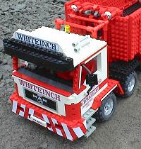
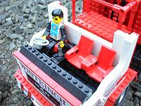
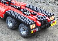
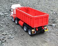
BodyworkThis model has more exterior detail than the previous ones for several reasons; it was a design direction I felt would be good to explore, and the acquisition of the Lego Model Team Racing Truck was a good inspiration and source of pieces of the right type in the right colours. There was also the fact that the real truck had a lot of detail on it as well - the real versions of my previous models are quite utilitarian and adding detail that is not present in the real thing does not seem quite right to me. Another first in this model is the use of stickers, something I had never bothered with previously, but they seemed highly appropriate for this model. Where possible I tried to create features using Lego pieces, such as the radiator grill and grey surround which uses the dubiously named SNOT (studs not on top) technique, inspiration courtesy of Huw Millington's "Long Nose Diesel" locomotive. The stickers were created in a computer paint program and printed onto sticky labels on an inkjet printer. The skip itself was the result of a considerable thought and design - as with real skips, it should be as light as possible without compromising structural strength. From this, I decided to create the sides from vertically placed plates rather than a wall of bricks, the plates being held against a sparse frame of Technic beams with 1/2 pins. After obtaining several 6x12 red plates at a recent Legofest it prove quite effective - when built from smaller 4x6 and 4x8 plates it was a bit unstable. Wing mirrors were something I initially tried to ignore as they are often flimsy and prone to falling off, which I find irritating in "working" models. However, the truck looked a bit bare without them, so something had to be done... and that something meant bending flex tubes beyond their tolerance to create the frames, which were attached in place using the standard clips. A small section of pneumatic hose was pushed onto the frame, and then the "mirror" itself, a 2x2 plate with holes on the back, was pushed onto this. As a result, the wing mirrors are genuinely adjustable! Since the model is to Technic figure scale, it has the proper cab seating arrangement of three abreast with an offset gearbox between the driver and passengers. This is in contrast to the low loader truck based on Lego set 8872 shown on the compact excavator page, where the smaller scale only allows two adjacent seats. As ever, some compromises had to be made. Perhaps the most noticeable of those are the mudguards, which are rounded in the real truck but made from several straight sections in the model. The reason for this stems from the philosophy of it often being better to model something simple well than something complex badly; I had tried to make rounded versions but they didn't look that great and were very flimsy. In any case, mudguards made from straight sections in exactly the same way as my model are very common on other trucks of this type, so I have some justification at least! Finally, a confession. There is a catwalk on the truck behind the cab with a ladder leading up to it, the purpose of which I have no idea. I assume it is for inspection of loads, or perhaps to assist in covering the load with a tarpaulin, but I am probably completely wrong on both counts. |
|
|
|
|
|
|
|
|
|
|
|
|
|
Click on pictures to
enlarge |
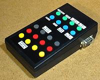
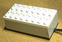
Radio ControlThe radio control system is a prototype custom built and designed by John Barnes, which he sent to me for testing and evaluation just after Christmas. Communication is by proper radio control, not infra-red, so a direct line of sight between transmitter and receiver is not necessary. The receiver brick is capable of controlling up to eight independent 9V channels, two of which are designated as "heavy duty" and are capable of driving multiple motors in parallel. This unit has dimensions of 8x4x2.66 studs, very similar to the small black 9V battery box, with eight standard 2x2 Lego electrical connectors fitting directly on the top. For legal reasons the production version of this unit available on the HiTechnic website is a four channel unit, however, those are available at two different frequencies with corresponding transmitters and therefore can be combined in one model to give eight channels - this was the method I used in the All Terrain Crane model which has seven radio controlled functions. The receiver is powered by an external battery source to allow the builder to choose the type of battery box best suited for their application. This also allows non remote controlled devices such as pneumatic air compressors to be powered from the same battery source, saving space and weight. The control unit has 8 sets of buttons, one for each channel. Four sets have two buttons and are instantaneous, so the motors will move only when the button is pressed and held down. The other four have three buttons, one for forward, one for back and the other for stop, so continuous motion is possible without having to keep a button pressed down. On the truck this feature was used for the skip tipping/loading function. Finally, there is an RS232 port allowing the device to be connected on to a computer, which can then control the motors remotely. For further information on this device, please visit the High Technic Products website or contact John Barnes directly at barnes@sensors.com. |
|
|
|
Click on pictures to
enlarge |
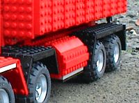
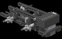
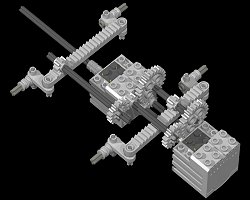
DrivetrainThe last gear reduction step in the drive train of a vehicle - the one which connects the drive train to the wheels - is known as the final drive. In most vehicles this occurs in the differential connecting the drive shaft to the driven wheels, but in some heavy duty vehicles further reduction is done in the wheel hubs themselves, often with planetary gears. This may appear to be inefficient as it increases the total number of gears in the system and therefore friction and complexity, but there are advantages. Since more gear reduction is being done in the axle and wheel assembly than usual, the drive shaft will spin faster with less torque. The latter is the important factor in this case, as the torque produced by a drive shaft in a very heavy vehicle, particularly when working off-road, can be so great that the resultant stresses can damage or reduce the working life of the vehicle. Another advantage of having the final drive in the wheel hubs is that less stress is placed on the differential, which can then be reduced in size allowing higher ground clearance, making the vehicle more effective in off-road conditions. Implementing planetary hub reduction in a Lego truck at a scale of 1:20 is probably not possible in a practical sense, but I still wanted to use the principle, particularly since the model is very heavy and has a long drive shaft, making the chassis prone to twisting. As ever, a compromise was reached; the total desired gear reduction was 9:1, so the first 3:1 stage was done where the drive shaft meets the differential. The second 3:1 stage is on the axle for each wheel - not planetary gears but they are nearly in the hub! As a result of this the drive motor at the front of the vehicle connects straight to the drive shaft with no gear reduction whatsoever at that point. |
|
|
|
|
|
|
|
Click on pictures to
enlarge |
SteeringThe steering on trucks with two front axles was the subject of one of those moments of sudden understanding you sometimes have as a child. The four axle crane I had built from an idea in an official Lego booklet had two front axles, both steering in sync at the same angle; however, when I saw one of the real trucks turn a corner I noticed that the second axle steered less than the frontmost one, and suddenly everything was clear. It doesn't seem like much now but at the time it was quite a revelation! Years later I have attempted to create the steering in this truck with a reasonably mathematical basis. Space in the front of the truck was at a premium so I did not implement Ackerman steering as found in some of the more advanced Technic sets, however, I did use similar principles to calculate the ratio of the second steered axle to the first. To do this, some dimensions of the truck were required, the axles of which are denoted by the numbers one to four, one corresponding to the frontmost and four to the rearmost:
Once those values were obtained from the MAN 35.364VF datasheet, the point on the truck which is perpendicular to the centre of the turning circle was calculated - on a two axle car with front only steering, this corresponds to a line straight through the unsteered rear axle. Since this truck has two unsteered rear axles, I made the assumption that they will slip equally when turning and therefore that it would be halfway between them. If this distance is added to the wheelbase it gives the distance from axle number two to the the centre of turning. When the front bogie spread is added to this, it gives the distance from axle number one to the centre of turning. Using these values and some simple trigonometry, as seen in the diagram to the left, it was calculated that axle two should be steered to an angle 4/5 of that of axle one - in other words, the gears connecting the steering mechanism of axle one to axle two should have a ratio of 5:4. With Technic gears this ratio can be obtained by gearing down the output of the first axle by first driving a 40 tooth with a 16 tooth gear (5:2) followed by a 16 tooth onto an 8 tooth gear (1:2), giving a total of 5:4. However, as mentioned previously, space was at a premium and 40 tooth gears are very large, so I settled on the ratio of 4:3. This was deemed close enough and achieved using a 24 tooth onto a 16 tooth gear (2:3) and then an 8 tooth onto a 16 tooth gear (2:1) giving 4:3. Since the chassis directly under the cab of this model contained two 9V motors and a battery box, the front bogie had a lot of weight on it. This highlighted a property of the new Technic steering pieces using a bracket with two pins going into the chassis; they tend to bend under heavy load. Eventually this became so severe that I reverted to the older style of steering using thin Technic plates, which are far more resilient to downwards pressure and have less backlash. I am happy with the way the steering turned out, particularly since full use was made of the turning capabilities of the steering pieces, unlike several recent Technic models which restrict the maximum steering angle somewhat. Given that the wheels used in the front bogie of the model are much wider in scale terms than those in the real truck, the only way to achieve this was to narrow the chassis to six studs wide at the front. |
||||||
|
|||||||
|
|||||||
|
|||||||
|
Click on pictures to
enlarge |
ConclusionsI really like this model, for many reasons; I think it captures the very British appearance of the real truck quite well, and feel that it could be easily remodelled into other types of truck due to the modular structure. The radio control device improves playability the truck tremendously when compared with the other models using umbilical control, for obvious reasons. Getting all the functions packed into the limited available space was a challenge as ever, and it is very satisfying to see them working in the same way as the real truck. On the downside, the model cannot load a particularly heavy skip, although packing material can be used as tipping fodder. This is due to the forces exerted on the boom lifting system which are surprisingly large; a pneumatic system would probably cope with this better, but there is no simple and compact way to control the Lego pneumatic valves electronically at this time. The pressure required for two pneumatic cylinders mounted in series to drive the boom linkage when loading the skip was enough to blow the hoses off the taps in any case! Still, I feel that demonstrating the principle is the most important thing for this in this case, and to lift the proper scale weight of 2.5kg is probably beyond the scope of Lego at this scale. When building this model I came across several interesting phenomena I did not expected to experience while doing lego engineering. Some of the earlier versions of the hook lift mechanism creaked and groaned in a very disturbing fashion, and one version even created serious oscillations and vibrations in the structure. Of course, you can often observe this when using components with elastic properties, but the components in question were not particularly elastic... Tolerances also became important - the pivot point for the tipping boom uses a standard axle to keep it in place. Why? Because when I used the friction pins to give a better fit the boom would no longer fit into the chassis. The room temperature effect on the rubber band in the boom lock mentioned previously was also unexpected. The model is surprisingly strong and has travelled the length and breadth of the UK by train in a carrier bag with only superficial and easily repaired damage occuring each time. One of the best tests was taking a beta version to a recent legofest which highlighted many initial weaknesses which were subsequently fixed. Oddly enough, the wing mirrors survive a lot more often than expected... John Barnes has recently developed some custom lead screw components which would be far superior to the rack system in strength and simplicity for the tipping and loading functions of this model. Essentially they are electrical replacements for the pneumatic cylinders, and having recently received some I am severely tempted to go for a retrofit attempt. Watch this space! |
|
|
|
|
|
Click on pictures to
enlarge |
DAT File DownloadIndividual modules:
Combinations of the above:
|
References
|
