
Click on pictures to
enlarge |
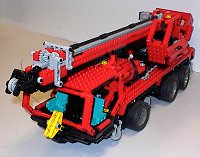
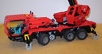
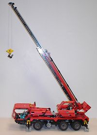
InspirationMobile cranes are ubiquitous on construction sites nowadays, and somehow seem to be ideal targets for modelling with Technic Lego. Perhaps it has something to do with their apparent technical unseemliness; as a child, before I had a more formal grasp of mechanical engineering principles, I could never figure out why they didn't fall over! Nowadays, even with a better understanding of such things, it is still a challenge to create a Lego mobile crane that works well and more to the point, looks good. Sometime around 1980 I purchased Lego Set 855 in a sale with some Christmas money, and I thought it was great at the time, despite having several limitations. The outriggers were more cosmetic than functional, collapsing under very little strain, and I preferred the truck type crane to the single cabin type represented by this set. There was a model of this type based on the 855 set outlined in the "ideas" section in the instructions of some other models, but it too suffered from a large degree of flakiness. Nonetheless, the workings of the boom and superstructure were superb, and were part of the inspiration for the boom on this new model. A more recent Technic Lego set, number 8460, provided the main motivation for this model. Unfortunately I didn't get this set when it was available, so I thought it may be possible to recreate it with my existing Lego pieces and the instructions on Brickshelf. However, I soon grew bored of that idea and thought it would be great to build a crane based around the 8460, but with many of the functions motorised... then I thought it would be better to motorise all the functions; then even better to redesign and lengthen the exterior using the more streamlined parts in from my 8448 Supercar. In the end, I based the design of the outriggers and boom around that of the 8460 with a quite a bit of modification, particularly on the internal workings, and the rest ended up as my own design. As a guide, particularly with regard to proportions and style, I used the Liebherr LTM 1060. This particular crane was useful as it was around the right size for my intended model, and had a modern and streamlined look that I felt could be captured well with the pieces from the 8448 Supercar. Observant readers will note that the LTM 1060 has 4 axles whereas my model only has 3, the reason for this being that I only had six wheels of the type I wanted to use. Having one less axle also provided more room in the chassis, making it easier to fit several of the crane functions, a reason which was of course secondary in consideration to the lack of wheels... |
|
|
Click on pictures to
enlarge |
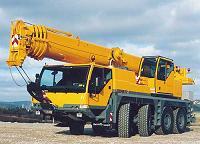
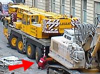
OutriggersThe outriggers, retractable legs that protrude from the side of a crane and some other construction vehicles, serve two purposes. The first is to widen the base of the crane so that the total centre of gravity of the crane and load can move further out from the centre of rotation of the boom before overbalancing. This allows heavier loads to be lifted at a given radius, the horizontal distance from the load to the centre of rotation of the crane superstructure. The crane can be viewed like a see-saw, with the the counterweight at one end, the load at the other, and the fulcrum or pivot at the centre. Extending the outriggers is equivalent to moving the pivot closer to the load, allowing a greater load to be lifted for a given counterweight. The second purpose is to provide a stable lifting platform, which the vehicle itself cannot do due to the wheels being pneumatic and mounted to the chassis with suspension. This is of great benefit when the vehicle is moving, but would cause severe instability when lifting. Some special types of crane can operate when moving without outriggers, but those tend to be far more limited in their reach and lifting capacity, or less mobile. In some small vehicles, the outriggers are manually operated and locked into place, but on larger cranes they are generally hydraulically operated. They can be set to different heights on each side of the crane, allowing it be positioned on the level even if the crane is parked on a slope. The outriggers on the Lego model are manually operated by turning a handle on each side of the crane, and are a blatant ripoff of those on the official 8460 Lego set. The reason I used that design instead one of my own is that I couldn't come up with a better one, and I had no intention of reinventing a worse wheel. The design really is superb, with the outriggers actually mechanically locking into place when fully extended. However, I did have to do some internal reworking to make them fit into my model, so there is at least some of me in them. Originally I wanted to motorise the operation of the outriggers, but in the end did not have enough motors, and decided to operate them manually as they are the least frequently used function of the crane. Motorising them in practice would be pretty easy in any case, although a large amount of gearing down would be required. However, in the end I was vindicated as the outriggers on a real crane, the Demag AC205, as seen in the photo to the side, actually need a tiny bit of manual adjustment when being stowed as well! |
|
|
|
|
|
|
|
|
Click on pictures to
enlarge |
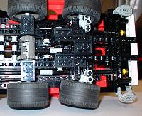
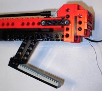
SteeringModern all terrain cranes tend to have multiple wheel steering, which reduces the turning circle of the vehicle thereby increasing manoeuverability, as well as reducing wear on the tyres and drive components. This can be essential as they often have to work in confined areas with many obstructions which normal large vehicles would have difficulty negotiating. They generally have two main modes of operation, coordinated and crab steering, although some have "rear wheels only" and "front wheels only" as well. Coordinated is perhaps the most obvious mode, with all axles turning in such a way as to minimise the turning circle of the vehicle. All the wheels of the vehicle, except perhaps those on the centre axle, rotate so that they point inwards to the desired turn, bringing the intersection of the lines drawn perpendicular to the wheels closer to the body of the vehicle. This gives the effect that the rear wheels steer in the opposite direction of the front wheels, and that on a many axled vehicle, the wheels closer to the centre of the vehicle turn less than those closer to the front or rear. Crab steering involves making all the wheels rotate at exactly the same angle, allowing the vehicle quite literally move sideways. This is exceptionally useful for manouevering in tight spaces, and would make parallel parking a breeze. I only implemented coordinated mode on the Lego crane, as providing a mechanism to switch between crab and coordinated mode on a model of this scale would be very difficult. Because the middle axle on the model is fixed, and the rear axle is closer to it than the front axle, I geared down the input to the rack and pinion system for the rear axle steering by 50%, meaning that the rear wheels turn half as much as the front wheels. The system worked incredibly well; there was none of the usual increase in effort required to propel the vehicle which usually occurs when one has two or more fixed rear axles, and the turning circle was impressive for a vehicle of this length. One of the problems I encountered in making the steering system was a lack of specialised steering pieces such as those found on the 8460, so I had to roll my own using the "camera" pieces found in the 8448. The resultant linkage was quiet nice, being multi jointed as opposed to the simpler parallelogram scheme, although there was a little bit of backlash and the wheel envelope was larger than when using the specialised steering pieces. Still, it was exceptionally robust and worked, so I was happy. Initially I had toyed with the idea of making all the axles powered as well as steered. I quickly dropped that plan in order to preserve my sanity. In the end the middle axle was driven by the new 9V type minimotor, and the front and rear axles were steered, giving a 6x2x4 configuration. Power was provided for steering by a micromotor (see the picture to the left) which used a belt as part of the drive train to the axles. This was necessary as the micromotor tends to jam when reaching the end points of steering, requiring manual intervention to get it moving again. The belt provides a clutch type mechanism which starts to slip when the torque gets too high, i.e. when the wheels have steered to their extremities. |
|
|
|
|
Click on pictures to
enlarge |
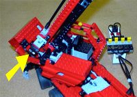
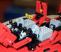
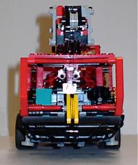
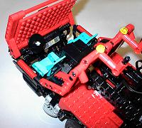
SuperstructureThe superstructure generally refers to the rotating part of the crane containing the second cabin and boom. Strength and stability is a must for the creation of these structures, otherwise the crane will easily collapse. A great deal of stress is put on the turntable ring as well as the boom lifting apparatus, therefore a lot of planning is necessary in the design of those parts to prevent failure. There is a chain of elements which must be securely braced and attached to each other, starting with the outriggers, which connect to the chassis, which connects to the turntable, which connects to the superstructure which is finally attached to the boom. Bad design in any of those sections will render the crane unusable. The above constraint caused a lot of difficulty in designing the rotating cab - not only did it have to be super strong, I also had to fit three motors in as well as a rack and pinion lifting system for the boom. In addition to this, if full 360 degree rotation of the superstructure was to be possible, it had to be very compact, fitting into a 12x14 stud square. After all this, it had to look the part as well. Fitting the two main motors with their associated gearing took a vast number of iterations before I finally had it working properly. One of the old style 9V motors was responsible for raising and lowering the boom, the other for raising and lowering the hook. Worm gears were used to provide a high gearing down ratio in a compact space, as well as preventing the boom and hook slipping when not in use. As well as being powerful enough to perform those functions, I wanted them to operate at a realistic speed - yet another constraint. The solution involved mounting the motors symmetrically on each side of the cabin, which gave a pleasant aesthetic aspect, as well as making concealment easy. The motor for the hook ended up being geared down 24 times, and the boom motor 216 times. The latter allowed the boom to be lifted with a heavy load, even when torque is highest at the horizontal. The bracing on this structure was so strong that when the boom jammed at one point, an 8 tooth gear shattered and pinged across away at great velocity instead of the Lego coming apart as expected! |
|
|
|
|
|
|
|
Click on pictures to
enlarge
|
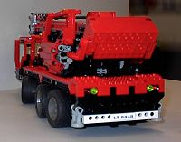
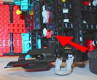
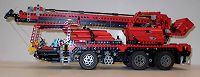
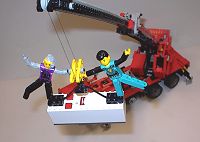
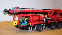
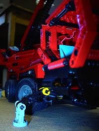
BoomMost mobile cranes have a telescopic boom consisting of four or more segments which can be extended to amazing heights. Occasionally a lattice boom, normally stored alongside the main section of telescopic boom, is fixed to the end of the telescoping section to provide extra height. This can be a simple extension or a "luffing" boom which can be moved up and down independently of the main boom, providing increased horizontal range. Due to the size constraints of Lego, it is only really possible to have a boom with one telescoping section on a model of this scale, the problem being that the width of the boom must increase by two studs for each section. Still, it is the principle of the thing that really counts, and a working two section boom is better than none. While the boom is based around the design of the 8460, several modifications have been made. First of all, the length was increased by 50%; while in theory this was a simple modification, in practice some reinforcing had to be done to make the boom viable at this length, as it had begun to sag and twist too much. In addition to this, instead of operating the telescoping section manually, a micromotor attached to the base of the boom was used, with a small 9V battery box concealed as a counterweight to the rear of the superstructure. As mentioned in the superstructure section, the whole boom was raised and lowered by a rack and pinion system powered by an old style 9V motor. This arrangement worked exceptionally well, as the boom could be raised and lowered from its extremities, even at full extent with a significant load. The hook was raised and lowered by another old 9V motor mounted parallel to the boom one, as also mentioned in the superstructure section. From the photos, it can be seen that the whole arrangement was very effective, being capable of lifting a large 9V battery box, containing 6 AA batteries, at full extension and significant radius. The superstructure would also rotate perfectly well with this load, although the creaks emitted were sometimes a little disturbing... The main limitation was the strength of the boom itself - the bend in the boom in the photos was actually there and is not a trick of the camera. This was partly due to limitations of the design borrowed from the 8460, but more on that later... |
|
|
|
|
|
|
|
|
|
|
|
|
Click on pictures to
enlarge |
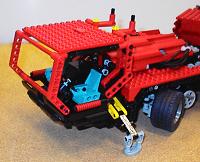
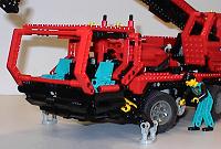
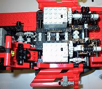
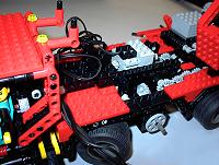
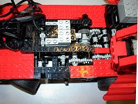
CarrierThe carrier consists mainly of two sections, the chassis and bodywork. The chassis contains all the electrical and mechanical workings and bears all the loads placed on the crane, whereas the bodywork is really just a cosmetic shell with no functional purpose. Separating the functions of the two sections allows optimisation of each - for example, when designing a strong chassis, one need not be overly concerned with aesthetics, and when designing the exterior one does not become bogged down in technicalities. It also allows subsequent modifications of either to be made more easily. Two motors were used in the carrier to provide three functions - one of which was a micromotor for the steering, as mentioned previously. The other was a 9V minimotor which went into a gearbox, allowing the user to choose between rotating the turntable or driving the crane backwards and forwards. I chose to multiplex those two functions as on a real crane they should never be performed simultaneously. The motor and gearbox arrangement can be seen in the photos, as well as the gearing system used to get power to the turntable, which was driven by a worm screw. The four wires for every function on the crane except boom telescoping (steering, drive/rotate, boom up/down, hook up/down) were gathered above the motor and fed to the crane control unit. The wires for the hook and boom were routed along the side of the chassis and up through the middle of the turntable, allowing full 360 degree rotation. In practice, the wires would probably get too tangled after a few hundred revolutions in one direction, but this never happened.
|
|
|
|
Click on pictures to
enlarge |
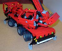
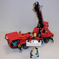
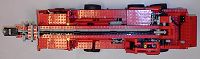
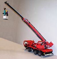
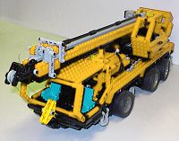
ConclusionsI was pleased with this model - in common with the LS160 it had that thing that made people want to play with it, which I think is really what it is all about The strength of the crane was amazing, although in some cases this caused difficulties. For example, occasionally a two block situation would occur when the hook reached the tip of the boom and the operator failed to stop the motor, resulting in the thread snapping. In real cranes this is an incredibly bad thing to happen, and can cause the boom to rise or buckle. To prevent this, "anti two block" mechanisms are used to automatically shut down the hook controls upon an impending two block situation. Perhaps something of this type could be implemented with the Mindstorms sensors or even a simple switch and built into a future crane model..? The red colour of the crane sometimes caused confusion, leading to the mistaken identity of a fire engine! The reason I used red as opposed to the more common yellow is that I only had the more modern Lego parts in red - all my yellow stuff dated back to 1980 or earlier - and indeed one does occasionally come across a red mobile crane such as those available from Sparrow Crane Hire. Through the miracles of modern image processing technology I have included a picture of what the crane would look like were it yellow. I was still not happy with the boom when those photos were taken and made some subsequent alterations making it far less susceptible to bending and twisting, taking it much further away from the design in the 8460. It also looked better, in my humble opinion. A metal hook like the 8460 would also have been nice, but now I am nit-picking. With the completion of the LS160, I think I reached my personal zenith with respect to skid steer loaders, and it is unlikely I will ever make one again. However, I do feel that I have another mobile crane in me yet. Perhaps more yellow? Or perhaps with three telescoping boom sections? Or drive and steer and suspension to all wheels? Crab and coordinated steering? Pneumatic outriggers? Only time will tell! |
|
|
|
|
|
|
|
References
Credits
|