Click on pictures to
enlarge |
Concept and History
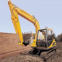
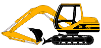
Excavators are everywhere, and come in all shapes and sizes, from the one ton mini excavator digging ditches at the roadside to the monsters weighing thousands of tons found in mines and quarries. They are all used for essentially the same purpose - removing material from a surface and placing it elsewhere. The nature and volume of material in question, and even the weather conditions, can affect the choice of excavator and type of digging apparatus used. While excavators were apparently used for dredging in ancient Egypt, the genesis of the excavator as we know it today was the Steam Shovel, patented by William Smith Otis in 1839. Steam shovels used a system of pulleys to move their arms and bucket, but otherwise worked on exactly the same principle as a modern hydraulic excavator. Prior to the advent of the steam shovel all earth moving, from digging small holes in the ground to civil engineering projects involving the movement of thousands of tons of material, had to be done manually by gangs of labourers. The steam shovel revolutionised the construction and civil engineering industries, bringing projects hitherto impractical into reality - Otis's steam shovel was said to be able to do the work of eighty men. Excavators were first mounted on the familiar caterpillar tracks at the beginning of the 20th Century, soon after the first practical tracked vehicle, the "Caterpillar Tractor" was demonstrated by Benjamin Holt. After 1930, steam engines were generally dropped in favour of the more efficient diesel or electric power, both of which remain in use today. It took a while before hydraulics were introduced in 1961 with the Orenstein & Koppel RH 5, leading to the familiar modern power excavator. |
|
|
|
|
|
|
|
|
|
|
|
|
|
|
|
|
|
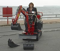
Click on pictures to
enlarge |
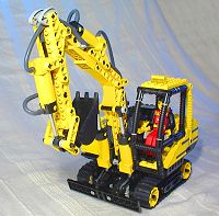
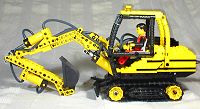
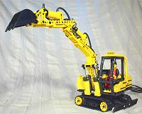
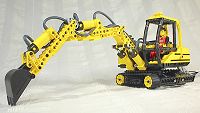
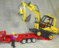
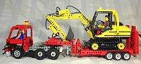
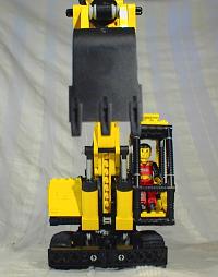
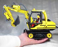
InspirationThe style of excavator I chose to model was easy - I had always wanted to make a tracked hydraulic excavator with all functions controllable, simply because this type is my favourite. Latterly, based on my experience building the mobile crane and skid steer loader, I also wanted all of those functions controlled "remotely" via an umbilical. The Technic Ideas Book (8888) has a blue excavator which looked superb for its time - I built it in yellow, but unfortunately the boom was very flimsy and not particularly impressive in action. It must be remembered, however, that this was before the Lego pneumatic elements were introduced, and attempting to create a hydraulic excavator boom at a small scale with only gears and levers was a very difficult task. Then along came the Excavator (8851), which looked a bit on the boxy side, but had pneumatics which initially offered great promise. However, they were only single acting units, and again I found the action of the model somewhat lacking. After this came the Wheeled Excavator (8837) with double acting pneumatics, but I wasn't interested in this one as it only had a single jointed boom, and obviously no caterpillar tracks. So, surprise surprise, the time came to make my own. All that remained was to choose a particular excavator to model. The choice was limited, as the only set of caterpillar tracks I had were those from the 8414 Mountain Rambler set, which are of a fixed length, and I wanted the excavator to be Technic figure scale. If we assume a Technic figure's real human equivalent height to be in the range of 5'6" (165cm) to 6'6" (195cm), then scaling the caterpillar tracks by an equivalent value gives them a possible range of 7'8" (230cm) to 9'(270cm). In excavator terms, this is very small indeed, and some companies do not actually make machines of this size; it is also far too large for a mini excavator, so that option was also ruled out. However, after a bit of searching I came across the ideal subject - the JCB JS70, smallest of the JCB range of tracked excavators, with a track length of 268cm - just right for a tall Technic figure! I also really liked the appearance of the JS70, and thought the cabin would be great to model with the new flexible Technic elements. A PDF format datasheet for the JS70 can be downloaded from here. |
|
|
|
|
|
|
|
|
|
|
|
|
|
|
|
Click on pictures to enlarge
|
Propulsion
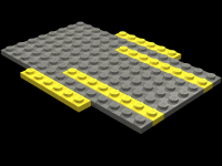
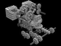
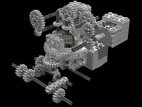
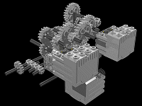
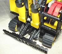
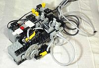
The real JS70 uses hydrostatic motors, one for each track, to drive and steer in a fashion similar to the LS160 Skid Steer Loader. Pressurised hydraulic fluid is fed to these motors from a pump driven by the diesel engine in the superstructure. This makes a lot of sense, as the motors are light and compact enough to be fitted directly on the undercarriage, avoiding cumbersome mechanical power transmission from the superstructure. Hydrostatic motors are not particularly efficient, but this is not really a problem as excavators are not expected to move quickly. The usual method of powering a tracked Lego vehicle, however, is to place the primary source of power for each track, an electric motor, on the undercarriage itself. While highly effective, I did not feel that this was a very good representation of a real excavator, with it's primary source of power, the diesel engine, mounted at the rear of the superstructure to act as a counterweight. So I tried to think of a method of having the two drive motors mounted in an equivalent position in the model, with their power being mechanically transmitted through the turntable, onto the undercarriage, and subsequently onto the tracks. To do this I had to find a way of getting two concentric drive shafts through a large Technic turntable, as well as still allowing a third power source directly onto the turntable for superstructure rotation. Fortunately, a search on Lugnet showed that Issac Merkle had already found a way to do this, saving a great deal of time and effort on my part. From this, I decided that the best approach would be to build the excavator in a "ground up" fashion - start with the undercarriage, then build a skeleton superstructure upon which the motors and boom would be fitted, then finally add the cosmetic exterior. Simple - or so I thought. I got my first inkling of the difficulty of this project as soon as I started the undercarriage - it was going to be very small and therefore very difficult to fit all the gearing in. Made to scale, the undercarriage had a length of 14 studs, a width of 8 studs, and a height of 3 studs, including the supporting beams, meaning that the drive train had to notionally fit into a space of 14x6x3 studs. As if this was not bad enough, the outputs coming from the turntable were bulky, adding additional constraints, and to add insult to injury, I then realised that the motor for rotating the superstructure would also have to be placed on the undercarriage. On top of that, I also had to fit the bulldozer blade on the right place - which of course, would have to be "tecnicified" in some way. Of course, it all had to be braced so that the pieces would stay together. There are a couple of interesting side effects from using this method of propulsion. First of all, assuming the drive motors in the superstructure stay still, a rotation of the superstructure relative to the undercarriage will actually move the tracks. Secondly, if the superstructure is not locked relative to the undercarriage in some way, then driving the tracks will tend to rotate the superstructure. The latter can be solved by using a worm screw as part of the superstructure rotation drive train; the former effect is not very pronounced in any case, so I decided just to live with it. Unfortunately, because of the differential occupying the entirety of the hole through the middle of the turntable, full 360 degree rotation of the superstructure as available on the Mobile Crane was not possible. Again, I decided that this was an acceptable compromise, particularly since the excavator can rotate in place on its tracks in any case. Last but not least is the bulldozer blade, an essential feature. There was just enough space left on the undercarriage to fit this, and it is automatically locked in either the up or down position with elastic bands. End stops are required in both positions to prevent the elastic bands pulling it too far; the undercarriage itself provides the stop for the down position, and a moveable axle resting on the top centre of the blade prevents it from moving too far up. |
|
| |
|
|
|
|
|
|
|
|
|
|
|
|
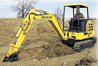
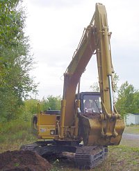
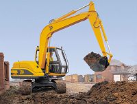
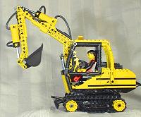
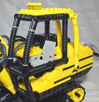
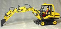
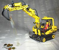
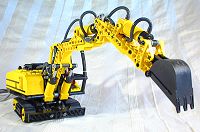
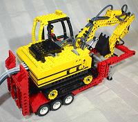
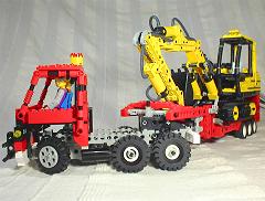
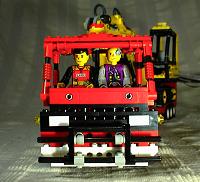
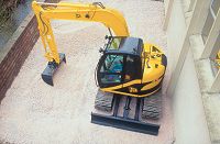
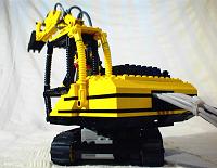
SuperstructureLet's start this on the most appropriate note - modelling the distinctive superstructure of the JS70 ended up being a nightmare of design and mechanical tradeoffs and compromises. Saying this, I am very happy with the result, but getting there was a saga of trial, error and frustration. You would not believe the number of times I had to tear down and rebuild the superstructure model to get it working properly and looking good. The first compromise reared its head when I attempted to fit the boom to the superstructure - because of the presence of the drive shafts through the centre of the turntable, it was not possible to attach the boom to the lower middle of superstructure as it is with the real JS70. There were two possibilities - either mount the boom higher or further to the front. I chose the latter as this is actually the most common arrangement on other excavators. The second boom problem came with the mounting of the pneumatic cylinders, something which is never as easy as it looks. The main boom on the real JS70 is moved by just one hydraulic ram; however, echoing this arrangement in the lego model prove impossible. If the cylinder was mounted with the hose attachment point facing upwards, it would foul on the boom; if it were facing downwards, it would foul on the undercarriage. The solution was to move the cylinder to the side of the boom, which allowed the attachment point to face upwards, out of reach of the boom. I added one on each side of the boom to provide symmetry and more power, and again I found this perfectly acceptable as most real excavators have this arrangement. Of course, those changes to the boom position meant that the mounting points for the boom itself had to be brought forward, which meant extending the superstructure forward. On the cab side, this made no difference as the cab is right at the front in any case, but the other side comes further forward than the real JS70. I had a hunch this may be useful for creating more space for the drive train anyway. The dual cylinder setup used more horizontal space than a single cylinder arrangement, so to minimize this effect I made the boom only one stud thick where it coincided with the cylinders, and attached it to the superstructure with 1/2 wide "L" beams at the top. For both functional and aesthetic reasons it was not desirable to have the chassis beams extend to the lower mounting point of the cylinders, so half beams and axles were used instead. A lot of thought was required to make this arrangement robust enough to cope with the stress exerted by the boom and pneumatic cylinders. Fitting the drive train was also difficult. From the plan on the left of this page, it may seem like there was quite a lot of room, but the reality was very different. A gear reduction of 1:9 was necessary to move the vehicle at a realistic speed, and so I had to fit this gearing and two motors into the space available. Perhaps the greatest problem was bracing the structure, which turned out to be very, very difficult. Because the superstructure and the undercarriage are so close together, attaching the superstructure to the turntable without restricting the rotation was a real challenge. It had to be done properly - if not, the torque from the motors would rip the thing apart in seconds. From a cosmetic point of view, I am very happy with the cabin, and there is plenty of room for the Technic figure! I had to compromise on the rear of the superstructure, however, as it is almost spherical on the real JS70. I actually attempted this, but it did not look good on such a small model, so I went for a less spherical but better implemented alternative. Again, many real excavators have such an exterior, so it wasn't really a problem. Routing pneumatic hoses can actually be a somewhat bothersome process, and this one was no exception. In fact, in common with the rest of this model, it was exceedingly difficult. There are a total of 6 hoses, all which had to go from the boom to the rear of the vehicle, where they are clumped together with the wires from the three motors into a rather fat umbilical. I managed to get two of the hoses routed along inside the superstructure; there was simply no room for the rest, so I routed them over the superstructure, into the engine compartment, then out the back, in the style of the Liebherr excavators. To make things neater, I added a small black bonnet similar to that on the larger excavators in the JCB range as well as the Hyundai pictured at the top of this page, which can be hinged back for easy access. The best thing after all this effort was that the idea actually worked! Believe it or not, the vehicle actually moves very effectively, and the superstructure can rotate through 180 degrees. Due to the motors at the rear of the superstructure acting as counterweights, just like the diesel engine in the real thing, the boom when fully extended can lift an equivalent of 854kg in its bucket. The real JS70 manages 1080kg, which I think is pretty close! |
|
|
|
|
|
|
|
|
|
|
|
|
|
|
|
|
|
|
|
Click on pictures to enlarge
|
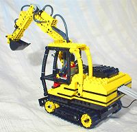
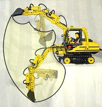
Digging
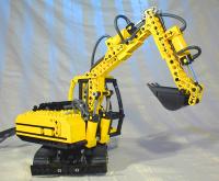
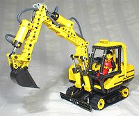
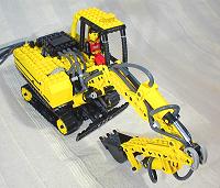
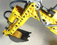
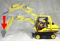
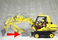
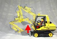
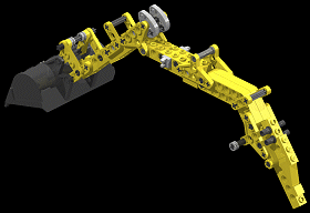
The digging implement on most hydraulic excavators consists of three sections - first of all is the boom, which is attached directly to the superstructure. Then comes the dipper which is attached to the boom, and finally the bucket which is attached to the dipper. There are hydraulic rams between the boom and superstructure, the boom and dipper, and the dipper and bucket. While the whole arrangement is commonly referred to as an arm, it is in reality more akin to a human finger, with the bucket corresponding to the fingertip. As mentioned in the concept section, all excavators dig using the same principle. The bucket is pushed into the ground with force, which in this type of excavator is provided by the hydraulic rams operating the boom as well as gravity. The bucket is then pulled through the ground towards the excavator using the dipper. This is a crucial moment, as the hydraulic rams moving the dipper have to be capable of providing enough force to pull the bucket through the ground then back out at the end of its sweep. The power of an excavator in this regard is known as its tearout force. Once the bucket has been torn from the ground, the boom is used to raise the bucket and deposit the load elsewhere, and then the entire cycle is repeated. Some excavators have the option of a having a longer dipper fitted; while this will extend the working envelope of the excavator, it should be noted the the tearout force will be correspondingly reduced. Different bucket sizes are also available, and each is applicable to the excavation of different types of material. Generally, the tougher the ground being excavated, the smaller the bucket must be. The largest buckets tend to be reserved for excavating very low density materials such as those in ditch maintainance. The Lego pneumatic elements are a very good analog to hydraulic rams, in that they have a very high power to weight ration, making them ideal for mounting on the excavator arm, where an electric motor would prove too heavy and bulky. Hydraulic or pneumatic hoses provide a flexible method of delivering power from the base of the excavator to the rams located on the boom. The only real difficulty with the Lego pneumatic elements, as mentioned in the Skid Steer Loader section, is that they only come in two different sizes which are not always ideal for the application one has in mind. For this excavator, the maximum power possible for the boom, dipper and bucket was required, which ruled out using the small pneumatic cylinders. The larger ones are powerful enough, but their stroke did not match the equivalent on the real JS70. Nonetheless, through judicious use of levers and different mountings, a working range close to that of the real JS70 was achieved. |
|
|
|
|
| |
|
|
|
|
|
|
|
|
|
|
|||||||
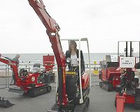
|
Click on pictures to enlarge |
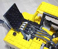
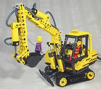
Control UnitThe lego JS70 is controlled via umbilical with an expanded version of the control unit used in the Skid Steer Loader, the main difference being the addition of one extra old style 9V motor to provide more power and faster pneumatic operation. As well as this, two extra switches have been added, one pneumatic and one electric. The three grey pneumatic switches control boom, dipper and bucket operation respectively, while the three yellow electric switches control the left track, right track and superstructure rotation. |
ConclusionsI have to say that building this model was very, very challenging indeed. Nothing came easily, as every aspect needed a quite remarkable amount of building and rebuilding before I was happy with it. Part of the problem was due to the size of the vehicle, which is even smaller than it looks; the volume available in the superstructure was less than that in the 8851 kit, making the space constraints utterly horrendous. Room had to be found to fit two motors and 1:9 reduction gearing, a large Technic turntable, the boom and its associated pneumatic cylinders, six pneumatic hoses, a cab which could accommodate a Technic figure, and perhaps trickiest of all, bracing to hold all of those in place. Of course, with all this, it had to look good, which meant sloped bricks on the exterior and a corresponding reduction of the interior volume. From the outside, the superstructure appears fairly high, but it has to be noted that building within the bottom brick level was off limits as it would cause the superstructure to snag on the undercarriage when rotating. Creating the undercarriage was no better - the area available for the gears transmitting power from the concentric drive shafts through the turntable to the driver wheels was miniscule, and at one point I even wondered if it was possible at all. In addition to this, a motor had to be fitted to rotate the turntable, and some form of bulldozer blade was really necessary, otherwise I would have felt the model to be a copout. Fitting a motor to rotate the turntable in the extremely limited volume was amazingly difficult; I went through many solutions, some of which were pretty desperate, before I settled on one that was effective. Much of this difficulty was of my own making, however. Had I decided to use the traditional approach of having two motors in the undercarriage to drive the tracks and one in the superstructure to rotate it, things would have been far simpler, the drive trains would have been more efficient, 360 degree superstructure rotation would have been possible, and a cosmetic appearance closer to the real JS70 would have been achievable. On the other hand, I had a concept, and I ran with it until I made it work, which was immensely satisfying. At one point I must confess to being close to giving up and resorting to the methods described in the above paragraph, but I couldn't do so in the end as I wanted to make an excavator with something just a bit different. The best part of all was when I derived the load capacity of the bucket and scaled it up to find it corresponded very closely to that of the real JS70. Somehow the fact the model was mechanically correct in this regard made it all worthwhile - it was, after all, the whole point of the exercise! |
|
|
|
|
|
| |
|
|
|
|
|
|
Click on picture to
enlarge |
DAT File DownloadIndividual modules:
Combined modules:
Those are the only DAT files I have for this model, however William Howard has full DAT files for his interpretation of the excavator and skid steer loader which can be downloaded from here. |
References
|