
Print quality instructions are available from my store and Rebrickable
Click on pictures to
enlarge |
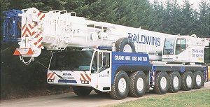
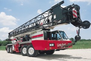
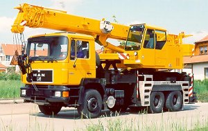
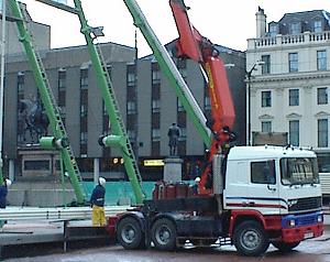
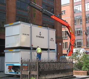
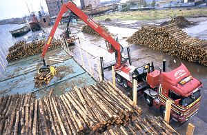
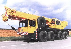
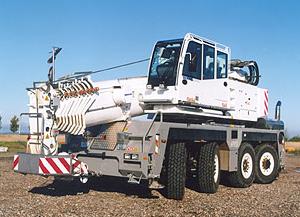
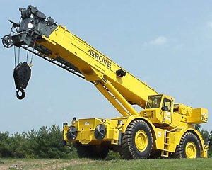
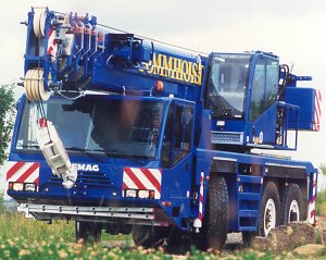
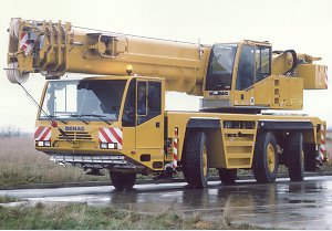
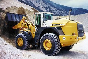
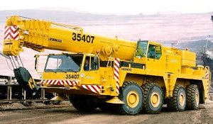
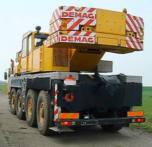
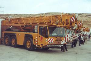
IntroductionAt first glance there may be a temptation to generically refer to all cranes with wheels as mobile cranes, and certainly this is true, or at least I have yet to find a working one with wheels that does not move. Yet within this category there are many subdivisions, and while there does not seem to be any globally accepted formal taxonomy, I'll attempt to describe what seems to be a common consensus of types. The Demag AC50-1 modelled here is known as an all terrain crane, another example of which is the Demag AC535 shown to the left. Features characterising all terrain cranes include specifically designed carrier vehicles featuring large single tyres, with most or all axles steered and many driven. These features, in addition to high ground clearance which can often be varied by raising the suspension, make all terrain cranes ideal for both on and off road travel. A disadvantage of this type of crane, however, is that they are generally more expensive to purchase and run than other types. Reading the datasheets available on manufacturer's web sites for the latest versions of these machines illustrates how complex and advanced they are, often with an amazing amount of computer, electronic and hydraulic integration making their operation safer and more efficient than the cranes of only five years ago. Perhaps the nearest relative to the all terrain crane is the truck crane, for example the Link-Belt HTC-8670 shown in this section. The carrier is still designed with a specific crane superstructure in mind, and while at first glance it may not look like an ordinary truck, underneath the skin the chassis has a great deal in common with standard truck types, albeit rugged ones, having similar tyres, rear wheel drive and front wheel steer. This configuration makes them faster and more suitable for long distance road travel, but they are less manoeuverable than all terrain cranes and have poorer off road performance. They are cheaper to buy than equivalent all terrain cranes and have lower operating costs given the right working circumstances. Next in line are truck mounted cranes, a configuration in which one manufacturer supplies all the crane components including superstructure, boom, outriggers, hydraulics, and sometimes the crane engine, while the truck is a standard type from another manufacturer. These are often useful for relatively light duties such as the assembly of prefabricated houses and could be cost effective for those not running large fleets of cranes. Another very common type fitted to standard truck chassis are truck loader cranes, often seen on building supply vehicles where they are used for quick loading and unloading without the need to depend on lifting facilities being available on site. These tend not to have cabs and in the UK are often operated from the side of the truck, although remote control is possible on some models. These are versatile cranes with a myriad of uses, and some heavy duty ones are capable of lifting substantial loads. Fitting somewhere between truck and all terrain cranes are the relatively new and strange looking city cranes such as the Demag AC60 featured on this page; a moment's thought will show where this odd appearance comes from, however. While most all terrain and truck cranes have two cabs, one for the carrier and one for the superstructure, the vehicle can be made more compact, less complex and less heavy by having just one cab on the superstructure. Traditionally, however, the problem with this arrangement is that the driver's view to one side of the vehicle is obscured the crane boom, making driving extremely dangerous. I suspect this is the main reason for making the boom sit low in the chassis of the vehicle, giving the driver a clear view to the front and both sides. As a side effect, overall height of the vehicle may also be reduced, an advantage for some urban work and travel. City cranes tend to have a drive/steer setup similar to all terrain cranes, yet try to approach the economy of truck cranes. Last but not least are rough terrain cranes, leviathans of the mobile crane world. These huge machines come in many capacities and are extremely capable off road, yet require transport on the back of a low loader to get them from site to site. Part of the reason for this is their slow speed and heavy axle weight, but in addition to this there is also the problem mentioned in the above paragraph about driver view - since these machines tend to have only one cab on the superstructure, it is impossible to see to one side of the crane due to the boom obscuring the view. |
|
|
|
|
|
|
|
|
|
|
|
|
|
|
|
|
|
|
|
|
|
Click on pictures to
enlarge |
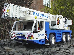
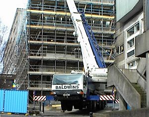
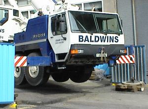
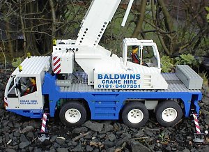
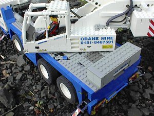
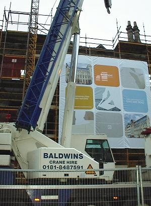
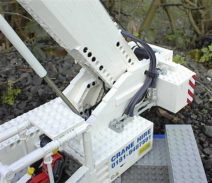
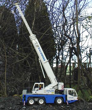
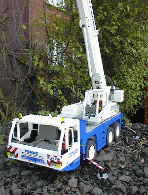
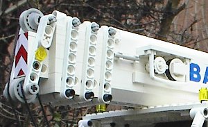
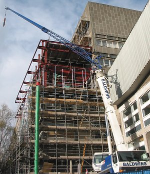
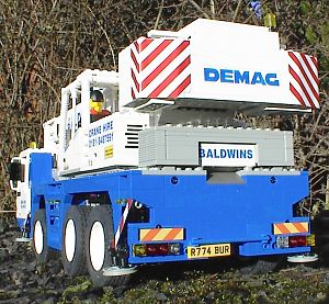
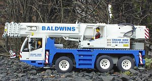
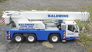
InspirationSome time ago I was browsing on the Demag web site when I came across one of their newer cranes, the AC50-1. As with many Technic enthusiasts the construction of another crane is a constant possibility, and this one really appealed to me; it looked small, compact, and very modern. The temptation when building an all terrain crane is often to go for the larger variants with many axles, yet for some reason this was the one. I suspect it had to do with the appearance, the fact that since I don't have a car I have to transport these models on the train, and also the challenge of fitting everything into a smaller model. After all, this one has just as many functions as a six axle crane yet approximately half the space to fit them in! The livery really had to be Baldwins; while they do not to my knowledge actually have an AC50-1 in their fleet, Baldwins cranes are often working in Glasgow city centre so I had many opportunities to take photos, providing a good source of material for this model. I also liked the Baldwins colour scheme, thinking it would make a good change from the standard yellow cranes. While the blue they use is much darker than the Lego blue, you just have to have a Henry Ford colour approach in this regard. |
|
Click on pictures to
enlarge |
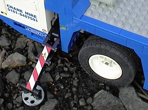
SteeringThe default AC50-1 from Demag has a drive/steer configuration of 6x4x2, and while a 6x6x6 option is available I decided to take the simpler approach, essentially because I also wanted to include suspension on the model and to do this with a 6x6x6 configuration with standard components and still obtain a good steering lock would have been impossible. In reality it is still not possible to get a decent steering lock with a driven axle even using the steer/drive axle components found in Lego set 8466, and the backlash with these components is very high. Having decided that the front axle would have pendular suspension, I remembered seeing an implementation of this type of axle on the Model Team section of Ben's World of ABS; the axle was used to add suspension to the Lego 5571 Black Cat Truck, and had the intriguing feature of being built upside down, some which can be seen by looking at this picture from Ben's website. The advantage of mounting the axle upside down in the chassis is that the components holding the rack against the pinion can go above the axle rather than below it, improving ground clearance, and for this reason I also decided to use this approach. Here the similarity ends, however. Given that the model has no centre differential between the two rear driven axles, which makes steering more difficult, and that I suspected the 6x4x2 arrangement would cause significant tyre scrub, it made sense to make the best of the situation by having Ackerman steering. Traditionally this is done by adding an offset to the steering arms onto which a linkage is fitted, which is turn is fitted onto the rack, allowing the rack to move in a straight line. However, with Lego components being relatively loose, the extra linkages tend to add a lot of backlash, so I decided to try to reduce backlash and simplify matters by removing them, having the rack directly attached to the steering arms. Of course this meant the rack no longer moved in a straight line, but there was enough slack in the interface between rack and pinion to allow this angular movement and everything was fine. Sounds simple? Well not quite! The Ackerman offset in the steering arms that gave the best geometry happened to be 1/2 stud, and given that the single piece racks supplied by Lego only come in even stud lengths, this made the axle an odd number of studs in length. While making construction of the axle more complex, it actually turned out to be a blessing in disguise; due to the dimensions of the wheels, I was able to fit them only 1/2 stud away from the steering arms, reducing the area they need to turn and leading to an amazing steering lock using very little space. With an even sized axle the wheels would have had to be fitted one stud away from the steering arms, requiring either larger wheel wells or a reduction of the steering lock. One thing that caused me concern during the design phase was that having the entire front axle rotate about axle used for driving the pinion was that axle oscillations would have the side effect of steering the wheels. However, the effect is negligible. Once the chassis was complete it became apparent that tyre scrub due to only having one axle steering was very significant when steering at sharp angles, the fascinating thing being that due to their semi pneumatic nature the tyres behaved in a very similar manner to real ones. I am almost certain they are wearing down! One of these days I'll build a crane with multi axle steering like this four axle example on the Demag web site!
|
|
|
|
|
|
Click on pictures to
enlarge |
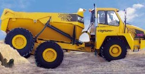
SuspensionCreating suspension on Lego vehicles has always been a challenge for many reasons, the main one being that it is incredibly difficult to get the right amount of spring in the system. Too much and the suspension ends up stiff and won't do its job at all, too little and your vehicle will sink to the ground - with either or these outcomes you'd have been better off not bothering at all. Given that you are unlikely to know the weight of a model you are building in advance, and that there are very few strengths of spring available in the same size for easy replacement, fixing the above situation will almost certainly require a major redesign. As if this wasn't enough, Lego suspension setups tend to have a lot of friction which reduces their effectiveness - they can be quite "sticky", and they often take up a lot of room in a model. Based on all this I had a bit of a rethink of the purpose of suspension in the context of a Lego model. In real life it tends to serve two purposes, one of which is to ensure that all wheels are in contact with the ground at all times. The other is to iron out bumps and pits on the ground when moving for the comfort of both living travellers and mechanical components, both of which can be damaged by excessive vibration and shocks. Given that motorised Lego models tend to travel relatively slowly, thereby making shocks and vibration negligible, and that there are no people aboard, it seems reasonable to remove the comfy ride requirement, which leads nicely into the concept of unsprung suspension. So how does unsprung suspension work? Think about things with legs for a moment - there is only one such entity which is guaranteed to have all of its legs in contact with a surface in 3D space at all times without falling over, and that is a tripod. Everyone has encountered the rickety four legged table with one leg of the wrong length, and with no suspension on a four wheeled vehicle vehicle the same thing will happen. So how does a tripod translate into a car? Easy, see the three wheeled vehicle configuration in the picture at the top of this section, a vehicle which will always have all its wheels on the ground at any time. You may not want to be seen driving it, however. Fortunately turning this into a four wheeled vehicle which will always keep all wheels on the ground at all times is trivial - since the single front wheel is capable of rotating in two degrees of freedom (it can rotate in the usual way and also rotate about the longitudinal axis of the vehicle), all that is required is a two wheel system which behaves in a similar fashion. This is accomplished with a transverse pendular axle, a beam which has two wheels fixed on either side of a rotating joint, and it is this joint which provides the necessary longitudinal rotation. Adding more wheels is easy - the number of pendular axles needed to ensure ground contact of all wheels at all times is the number of wheels minus three. This is derived as the simplest case of three wheels requires no pendular axles, but every time another wheel is added you must add another pendular axle. There are many ways of doing this but I chose to demonstrate the concept in this way as you often vehicles of this type in the real world. The approach here is generally to add a transverse pendulum first, then a longitudinal one onto that, and then even after that another transverse one, but there is nothing to stop you doing it all with transverse ones, for example, a configuration sometimes found on low loader trailers. Unsprung suspension is not just for Lego models, it is often used in construction vehicles to ensure equal load on each wheel and also to offset the effects of varying loads, something sprung suspension is not always able to deal with. To improve driver comfort the cab or seat can be mounted on springs. After explaining all this, I'm now going to describe why I did it differently on the crane model. Given that the factory default AC50-1 has a 6x4x2 drive/steer setup, example (3) at the start of this section would seem to provide the ideal option. However, I suspected that making a driven pendular axle similar to that in the Moxy articulated dump truck would either be robust and consume a lot of space, or be compact but flimsy. In addition to this, both rear axles on the Moxy are driven by a single differential, and I really wanted to have a differential for each axle, which complicates matters even further. The solution was to think out of the box again - for what reason are more than two axles required in a vehicle? In the real world, road authorities set limits on the maximum weight a vehicle can impose on a single axle, and the only practical way round this is to add additional axles to ensure the weight is spread around the axles of the vehicle such that no single axle exceeds this limit. With a Lego model there are no such rules, however, so any fraction of the weight can be applied to any axle. From this, it occurred to me that a hybrid system would be possible based on the two axle configuration shown at the diagram in the start of this section, which would bear most of the weight, with the wheels on the centre axle being very weakly independently sprung and therefore bearing very little weight. This results in an undriven steered pendular front axle (possible), a driven independently sprung unsteered centre axle (possible), and a driven fixed rear axle (easy). The latter two can be built in a relatively small space leaving room for other functions in the crane. The initial plan for the centre axle was to at least ensure it would basically keep out of the way and not make traction worse than it had to be. Traction, amongst other things, is directly proportional to the force pressing two surfaces together. Therefore splitting a load equally over three axles instead of two will make the traction of each axle proportional to 1/3 of the load instead of 1/2. Thus a 6x2 vehicle has less traction than a 4x2, but a 6x4 has more than the 4x2. For vehicles with more than two axles, the amount of load on a sprung axle can be varied relative to other axles on the vehicle by adjusting the strength of the spring; a stronger spring will result in it bearing more than its neighbours. This property is used by some modern all terrain cranes to ensure an even distribution of weight on all axles of the vehicle without having to micro engineer the entire weight distribution of the whole vehicle to an insane degree. Since the middle axle spring on the model is not very powerful it does not bear as much of the load as the other two, and therefore has little traction, so it tends towards the 4x2 case. So why bother driving the axle if it has so little traction? There are two exceptions at the extremes of travel in the middle axle suspension. If the middle wheels are off the ground entirely then we have reverted to the 4x2 case with the front and rear wheels, which is fine as long as the rear axle is driven. However, if the rear wheels are entirely off the ground, which can happen when the centre wheels go over a large bump, for example, then we have again reverted to the 4x2 case but this time with the front and centre axles bearing all the load, and therefore having all the potential traction. In other words, if the centre axle is not driven in this case then the vehicle is stuck. In practice both these situations happen more frequently than this as only one wheel on a given axle has to be off the ground for the entire axle to lose traction due to the differentials. In the end I actually found it better to give the centre axle having more traction in general so the strength of the springs were significantly increased. Why make the front axle pendular and not the back? A benefit of the pendular axle is that if one wheel drives over a bump, approximately only half the height of the bump is translated to the the vehicle chassis. As the front axle is undriven I thought it would make sense to give this one the best immunity to bumps in the road. Another reason is that a driven pendular axle requires a drive shaft to go from the chassis to the wheels which is also the point of rotation of the axle, therefore there will be a lot of weight pushing on the drive shaft causing a lot of friction, which will lead to an inefficient drive train. In the real world this can be offset through the use of concentric bearings, but Lego do not manufacture such pieces. A steered pendular axle will of course require the drive shaft from the steering motor to the rack and pinion system to go through a similar weight bearing pivot point, but this is nowhere near as bad as it is not as the steering does not have to be as efficient as the drive train - it is used less often and slowness is not as noticable. Of course, you could avoid this entirely by having the motors actually mounted on the pendular axle for both steering and drive, but this approach was not practical for this model. The rear axle rather than the centre one was chosen to be fixed as having a longer unsprung wheelbase increases the stability of the vehicle. If you've managed to get this far, congratulations, and there are a
couple of downloadable videos which show the
suspension in action. |
|
|
|
|
|
|
|
|
|
|
|
|
|
|
|
|
|
|
|
|
Click on pictures to
enlarge
|
OutriggersI described the function of outriggers on the web page for an earlier mobile crane model here, and so will keep things brief in an attempt to avoid repetition. Dictionary.com defines the term "moment" within a physics context as "The product of a quantity and its perpendicular distance from a reference point". In this discussion, the quantity is weight and the reference point is the part of the crane in contact with the ground between the load and counterweight. In simplistic terms, there are two weights involved here; the combined weight of the crane carrier, superstructure and counterweight and the combined weight of the boom and load. When distance from the reference point is taken into account those weights become the stabilising and overturning moments respectively. As long as the stabilising moment is greater than the overturning moment the crane will remain upright, however, in real life things are not that simple and operators must take care that the overturning moment is not suddenly increased to dangerous levels by external factors such as wind or waves. Outriggers reduce the overturning moment and increase the stabilising moment by simply moving the reference point closer to the load (and further away from the counterweight and crane carrier). A good analogy is when you see people move their feet further apart to help prevent them falling over on rickety trains - the sudden movement of the train increases the person's overturning moment while increasing the distance between the feet increases the stabilising moment, and thus the person hopefully stays upright. A consequence of using outriggers on a crane is that the total weight of load and crane will be concentrated onto the area covered by the outrigger pads. This can reach very high pressures, for example the LTM1080 shown to the left could have 128 tons unevenly distributed on the outriggers, and for this reason extra large pads are often employed to distribute the weight over a greater area and ensure that the crane does not fall through pavements, sink into soft ground or crack surfaces. A similar consequence resulting from the superstructure being connected to the carrier which is then connected to the outriggers is that the chassis must be very resistant to the torsional forces exerted by the load. Very heavy mobile cranes avoid the need for a proportionately strong chassis by having the outriggers derive directly from the turntable in a star shape as opposed to the more usual "H" arrangement in this model. To ensure that the crane functions equally around the full 360 degrees of superstructure rotation and that all stability calculations are going to be relevant the crane must be totally level. To this end many new cranes have self leveling outriggers - the operator simply presses a button and the outriggers adjust their individual heights under computer control until the vehicle is level. Outriggers on most mobile cranes these days are hydraulically actuated and each can be independently controlled in the up/down and in/out directions if desired, a total of eight independent movements, allowing optimum placement under all conditions. Some simplifications were necessary on the model, however, the first being that independent in/out and up/down movement of each outrigger is just not possible with the components available at this moment in time and at the scale of the model. The only practical solution I could find which allowed true "hands off" remote control was the locking system used on the previous mobile crane, although this time I made it significantly larger. Given that there is only one safe point of outrigger deployment when using this approach, namely fully extended and locked, it made sense to drive all four outriggers from one motor, so eight functions have in effect been rolled into one. Obviously on this model there is going to be no self levelling, nor any levelling whatsoever for that matter. Development was frustrating; as the weight of the model consistently increased beyond expectations I had to keep redesigning the outrigger actuation mechanism to cope with the additional weight. They do, however, work very well, as can be seen by the weights lifted in other sections, and in this model are fundamentally necessary as without them the load will be resting on the suspension, which has a stabilising moment of virtually nothing. |
|
|
|
|
|
|
|
|
|
|
|
|
|
Click on pictures to
enlarge |
Drive TrainI suspected this model would be rather heavy when complete and therefore decided to employ two of the 9V gear motors to drive the model. Much of the drivetrain arrangement was constrained by the unsprung suspension scheme detailed above and the wheel layout of the real AC50-1, which as ever was not particularly friendly to Technic gears! Other than the gears creeping up the arms serving as the moving part of the centre axle suspension there is nothing particularly complicated here - from the motors to the wheels is a 9:1 gear reduction. Based on previous experience with bevel gears, which can introduce weak points and increase friction in a drive train, all the gears were kept facing the same direction. While it is not a particularly realistic model of a real drivetrain, it has proven very effective in utilising the power of the two motors, something which turned out to be somewhat necessary as the weight of the model soared beyond all expectations. I had planned to power the drivetrain and other carrier functions from a single 9V PP3 battery, but in the end this could not deliver enough current so two running in parallel were necessary. The real AC50-1 also has the front and rear axles driven, unlike this model which has the centre and rear axles driven. Following the example of the real thing would have been good but unfortunately impossible; I didn't have any components allowing an axle to be driven and steered at the time of construction, and while subsequent parts to enable this have since been released by Lego, the steering lock is nowhere near as good as can be attained with a non-driven axle. |
|
|
Click on pictures to
enlarge |
TurntableFor many years I had made turntables on Lego models using standard turntable parts, of which there are several, often surrounded by smooth plates to make it stronger and more stable. However, after seeing Beat Felber's implementation of a proper roller bearing turntable, similar to the thrust bearing in the "Boom Luffing" section, I realised that more efficient solutions could be achieved. Implementing a turntable similar to Beat's in this crane was never going to be possible - the carrier is not wide enough, and the axles driving the outriggers occupy some of the space that would be required by a continuous ring of roller bearings. In light of this I tried a compromise using the small tyres from traditional Lego town sets mounted on 1/2 bushes as roller bearings, which were then set in a very rough circle around the turntable. The superstructure then rotates on top of this ring of tyres. Of course this will not be as efficient as using proper bearings since a lot of friction will be present where the axle sits in the holes of the technic bricks, but the theory was that the friction would be more constant and less sticky than using tiles. Careful positioning was necessary to ensure "bumps" from the bottom of technic bricks and plates on the superstructure were not too pronounced. Unfortunately I could not find enough space to create a full continuous ring of those bearing assemblies, and had to fill in the gaps with tiles, so it is difficult to assess their effectiveness. Personally I think it has made an improvement, but I'll let you decide for yourself from watching the video of the turntable moving. In real cranes the motor rotating the superstructure is usually of the hydrostatic type and mounted on the superstructure itself, rotating round a fixed toothed lower ring on the turntable thrust bearing. In the model, however, I thought it might simplify superstructure construction by placing the motor in the crane carrier. While it certainly achieved this, it also made the carrier more complex, but ultimately I think it was the best decision. Having the motor in the superstructure would also have required the turntable to be mounted upside down, something I wanted to leave for another time. In the previous crane I used a worm screw directly onto the teeth of the turntable to effect slewing, but there is a lot of friction inherent in this approach. As this crane was going to be far heavier and capable of lifting far heavier weights, and I wanted to realistic slewing speed to be modelled, I decided to avoid using worm screws to maximise efficiency. Part of the problem in having an 8 tooth gear mesh directly with the turntable is that the gears tend to crunch under high torque; this was remedied by the creation of a custom part from a 2x4 technic plate which had one end rounded off allowing the 8 tooth gear to be braced from the top and bottom. I've wanted exactly this piece for years! To improve the stability of the turntable assembly a threaded axle was placed through the superstructure, turntable and carrier. This axle can be tightened and locked by means of the threaded nuts, but I am not convinced by the results of using it. the turntable performs well enough when the crane is at maximum capacity in any case, and tightening the nuts simply makes the movement more jerky. Perhaps with a Beat Felber style turntable this would not be the case, but I'll have to wait until the next crane to see! |
|
|
|
|
|
Click on pictures to
enlarge |
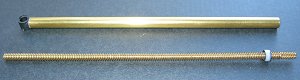
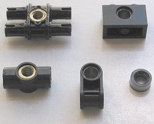
Remote Control and Custom PartsJohn Barnes' custom components from HiTechnic made a great deal of difference to this model, not least of all in providing a good way to get power from the carrier to the superstructure. As with many things, there is an easy way and a hard way to do this - the hard way can be seen on the Compact Excavator, the easy way is not to do it all. The latter can be easily achieved as HiTechnic have four channel radio control units operating at two different frequencies allowing them to be used simultaneously; usually this allows two model such as racing cars to be operated in a competitive environment, but there is nothing stopping you using them both in one model. One radio control unit is located in the crane carrier and the other in the superstructure, each with their own battery box, and therefore no wires or any other connections have to go through the turntable, allowing infinite turntable rotation. John had worked for some time on leadscrew components designed to interface with Lego, and had initially come up with some plastic versions which were very effective at short lengths but prone to buckle when longer. His solution was to come up with a brass leadscrew which would interface to plastic Lego through various reinforced standard components, some of which are shown to the left. A standard Technic cross axle is machined on the end of the leadscrew to allow connection of driving gears. While this is still a prototype system, I can see a great future for these components as they allow a degree of strength, precision and control simply not available using pneumatic parts. The fact that extremely precise positioning is achievable using the Lego RCX must surely be a boon to robotics enthusiasts. |
|
|
|
|
|
|
|
|
Click on pictures to
enlarge |
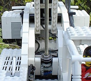
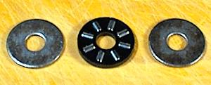
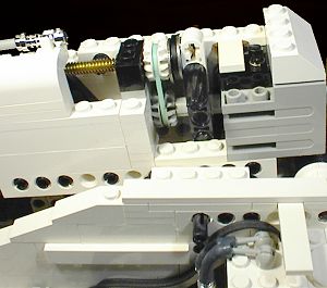
Boom LuffingThe vast majority of modern mobile cranes use hydraulic rams to luff the boom for the simple reason that they are the best means of applying very large amounts of force; they have high power to weight ratios and when in good working order are very efficient. The rams used for luffing on mobile cranes are often extremely powerful as they have to lift heavy loads at high mechanical disadvantage, see the picture to the left for an example. The Lego 8460 crane uses pneumatic components in place of hydraulics, but these were no use, not least of all because they were too small for the model. Pneumatics tend to have a lot of "bounce" in them which makes them extremely unsuitable for heavy or variable load applications where precision is necessary; and speaking of precision, precise control is impossible. A great replacement for hydraulics on the model came in the form of brass lead screws sent to me by John Barnes, one of which can seen in the photo to the left. The lead screw is simply a long screw with a cross axle machined onto the end to allow the connection of standard Lego gears, and this in turn goes into a tubular casing (painted white in the photo) which has a small threaded section at one end and an attachment similar to the Lego pneumatic cylinders at the other. Depending on the direction it is turned, the lead screw forces the casing upwards or downwards and thus actuates the boom in a manner analogous to the hydraulic on a real crane. Lead screws are not as efficient as hydraulics, but certainly far more practical (and less messy) at this scale! The leadscew offers good lifting capabilities with an amazing degree of precision, and can position the boom anywhere between 0 and 90 degrees to the horizontal, something I've never been able to achieve in any real sense with other methods such as the rack and pinion used on the previous crane. I enjoyed working on the mechanism driving the leadscrew a great deal, a picture of which can again be seen to the left. As the boom is raised or lowered, the angle the leadscrew makes with the superstructure also changes and so it is essential that the turning mechanism can cope with this. Initially I had tried to mount the motor inside a pivot which had the lead screw going directly into it, but getting the necessary gear reduction in the space allocated was not possible. The use of a universal joint to transmit power through various angles was also considered, but in the end rejected as the necessary range is nearly 90 degrees, and even if it was possible to mount the motor at the 45 degree angle necessary to make this work, universal joints behave in an increasingly non-linear fashion as they approach 45 degree angles in any direction. In the end I transmitted power from a stationary motor through a system of gears, the centre one rotating around the axis the pivot also rotates. The axle on this gear does not go all the way through the mechanism, however, it only serves to hold the gear and not bear the load of the mechanism itself, something which is done by 3/4 Technic pins on either side. This system worked well enough, but while I was developing it a colleague at work had been using a large thrust bearing for a project of his, and I wondered if a similar method could be used to reduce the large amounts of friction generated from the boom pressing the leadscrew onto the drive mechanism. Some research brought up a needle roller thrust bearing of an almost perfect size, with the inner diameter only slightly larger than a standard cross axle. With these in place, a huge efficiency increase was evident, and I'll certainly be using them again in the future for other applications. One thing you may have noticed is that the white painted cylinder and leadscrew are upside down when compared with a standard hydraulic arrangement. While not quite perfect aesthetically this makes sense mechanically; for hydraulics, the pipes and hoses feed into the thicker cylinder, so it makes sense to have this section nearer the superstructure where the hydraulic pump is located. For the leadscrew, it is more logical to have the thinner threaded section rotating; as well as allowing it to be placed in areas only one stud wide without fouling, this allows the rotating part to be fed through a standard axle hole - the right place for rotating parts. Since the luffing motor is located on the superstructure, obviously the leadscew should be closer to this than the larger section. I'm not entirely convinced that having the thicker cylinder rotating would be correct from an aesthetic point of view anyway. |
|
|
|
|
|
|
|
|
|
Click on pictures to
enlarge |
Boom TelescopingI have written previously about boom telescoping on the page for the previous mobile crane and perhaps more notably on the Ideas page on this website, where I described the implementation of a telescoping boom with more than two sections. Having three sections on this model was not possible however, since the boom is only 4 studs wide at the proper scale, and while I could have made it 6 wide I felt that getting the model looking correct was more important. While previous efforts had used rack and pinion systems to effect the telescoping motion, this time I decided to use a leadscrew of the same type mentioned in the "Boom Luffing" section as I felt it would be more compact and easier to fully enclose in the boom, as well as offering more precise positioning and a better analogue to what happens in the real world where hydraulics are again usually used. The screw is driven by a motor located at the bottom of the boom and travels the length of the first section of the boom; the telescoping section has a special threaded Lego piece attached to it base, and as the leadscrew is turned the telescoping section moves relative to the first section. This seems simple but there were many headaches! To ensure that the telescoping section did not bend I constructed it from two layers of beams, and while this was very effective in reducing bending under weight, it made the geometry of the boom a bit odd leading to difficulties transferring rotation from the motor shaft to the leadscew. In the end the only solution I could come up with was a belt drive which tended to slip too easily leading to unreliable telescoping. Initially I tried many combinations of elastic bands and different sizes of pulleys, but none were satisfactory. The next attempt utilised two elastic bands going round pulleys made from two bevel gears as shown to the left which did not slip at all; while not ideal this was better than slipping too often. However, if the motor stalled at the end of the telescoping travel, for example, it would not start again without human intervention. I put this down to having too much friction where the bottom of the leadscrew was pressing against the first section of the boom, and so fitted a thrust bearing of the same type as the one used for boom luffing. Unfortunately the problem persisted but then I suddenly realised that is was due to the two elastic bands used in the pulley drive becoming entangled when the motor stalled, requiring more force than the motor could provide to untangle them. The solution was to find a stronger and wider elastic band, and the green one shown in the photo, obtained from packing material, worked well. Recently I discovered that the Pit Droid set has even better ones, however, so purists need not be offended, at least in that regard. After all that, the thrust bearing did improve matters as well, so I kept it in. I do think that the elastic band could still be more powerful however, and I hope one day Lego consider releasing timing belts! |
|
|
|
Click on pictures to
enlarge |
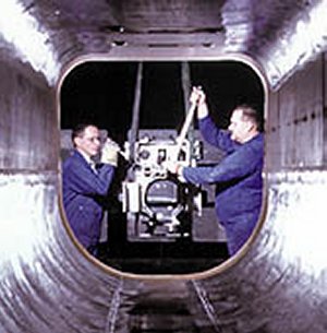
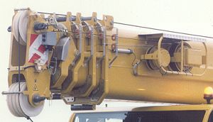
Boom DesignFor the same reasons that you do not find windows with sharp corners on aircraft, the booms on modern telescopic cranes tend to have rounded rather than rectangular profiles. The reason for this is that stresses in a structure tend to propagate to corners and edges causing metal fatigue and eventual component failure. A dramatic example of this can be read about in one of the world's first jet airliners, the De Havilland Comet. Many manufacturers have similar solutions to this problem on their telescopic crane booms; for example, to the left is show Demag's Ovaloid boom profile whereas Liebherr describe theirs as an Oviform boom profile. The boom on the crane model has a similar shape externally, but it doesn't add anything to the strength of the boom as far as I know - it really is just for show. Telescopic boom technology has advanced over time with improvements in metalurgical and microprocessor techniques - for a long time the best way to telescope multi section booms was with a single hydraulic cylinder in the first and second boom sections which operated a system of ropes to move the other sections simultaneously, as described in the Ideas section of this website. More recently, however, lighter and more efficient systems have been devised using single hydraulic cylinder to pin each boom section into place one at a time. The whole process is controlled by computer; the crane operator specifies the desired length or configuration of the boom on a computer console then leaves the machine to do the rest. The Demag AC60 uses this system, which is presumably instrumental in allowing it to have a nine section boom, something that would have been very difficult to achieve using the old rope based approach. Again Demag's UNIMEC and Liebherr's "LICCON Assisted Telescoping System" are conceptually similar ideas with different implementations, not least of all because of patent issues. You may have noticed cable drums on the side of telescopic booms - these contain wires, or a data bus in more modern implementations, and unwind as the boom telescopes. Their purpose is to transmit information from sensors and instruments placed at the tip of the boom to the control systems and displays in the operator's cab. Devices frequently employed are anemometers for calculating wind speed, angle sensors and limit switches for the hoist. |
|
|
|
|
|
|
|
|
|
|
|
|
|
|
Click on pictures to
enlarge |
HoistTo understand the operation of a crane hoist, it is perhaps best to start with the concept of line pull, the maximum permitted force that can be applied to a single cable line within required safety and functional parameters. Some obvious factors affecting this are the strength of the cable, the maximum torque exerted by the motor driving the cable drum, and the braking ability of the cable drum. The datasheet for the AC50-1 states that it has a maximum line pull of 43kN, equivalent to 4.38 tons. In other words, no matter what boom configuration and angle of elevation you choose from the load chart, with only a single line this is the maximum permissible weight. Fortunately it is possible to reeve the line round the pulleys on the boom and hook multiple times in the standard fashion, increasing the effective maximum line pull. The AC50-1 can be configured with 1, 3, 7 or 12 lines allowing loads of 4.3, 12.9, 30.1 and 50 tons respectively to be lifted, although obviously at a correspondingly slower rate. The maximum line pull on the model is 0.33Kg, which translates to 2.64 tons in the real world. Given that the real AC50-1 can do 4.38 tons, the model is not too far off! Another factor affecting line pull I came across when building the model is that as the cable winds onto the cable drum in successive layers, the distance from the centre of the drum to the cable increases, and therefore the mechanical advantage from the motor to cable decreases. In other words, the line pull of the hoist decreases the more cable is on the drum, and unless some form of variable gearing is used between motor and cable drum the maximum line pull will tend to be defined by the worse case, i.e. with the cable fully spooled onto the drum, and it was this approach I used for the model. This effect stung me once during the building process when I replaced a thin thread with a thicker one of equal length, and all of a sudden the crane was incapable of lifting a load it had previously managed. And therein lay another engineering compromise; I could use a thinner cable which did not stay in the pulley races well at all, yet in the worse case could lift heavier loads, or choose a thicker cable which sat well in the pulley races and provided a lesser line pull. Of course further tradeoffs can be made by having a thick but short cable, but a reasonable length of cable is required to make the crane useful. In the end I redesigned the motor to cable drum drive to allow the previous line pull to be achieved with the thicker thread, although obviously now by returning to the thinner thread an even better line pull could be achieved... Another interesting cable related side effect is that as the boom extends telescopically, the hook will rise relative to the boom tip by an equivalent amount, although this is obviously influenced by the number of lines reeved. This effect can lead to severe consequences in the real world such as the dreaded two block condition, where boom and hook come in contact with each other and cause serious damage. If the cable could be spooled at the correct rate while the boom was telescoping, it would keep the hook at a constant height and help prevent the two block condition. A simpler method could be to spool out the cable at the same rate the boom is telescoping; this will not keep the hook a constant height, but would prevent the two block condition arising. While either of these could be arranged mechanically, I suspect modern cranes use sensors and microprocessor control to do so, and while myself and colleagues have debated the best way to do this, I've yet to find any information about how it is actually done. If anyone could enlighten me I'd be very grateful! |
|
Click on pictures to
enlarge |
StrengthThe real AC50-1 can lift a maximum weight of 50 tons at a radius of 3 metres, quite an achievement considering that the crane itself only weighs 36 tons. However, as the radius of the lift increases, naturally the maximum lift capacity decreases. In the old days it was up to the crane operator to gauge when the maximum load was being exceeded; often the first indication that this was happening was when the crane started to tip over! The advent of mechanical load moment indicators in 1934 by Wylie Safe Load Indicators made judging loads a far less precarious affair and vastly increased the safety of crane operations. Load moment is conceptually similar to overturning moment, but is the product of load only (as opposed to load, boom and other contributory weights) and the distance from the load to the centre of the superstructure turntable (as opposed to the reference point defined by outrigger reach). At small boom heights and radii, the contribution of the boom weight to the overturning moment is small compared to the load, but as the boom is extended to greater heights and/or the angle to the ground reduced, this contribution becomes greater and therefore the maximum lift is reduced more than one might think. This can be shown from load chart on the left; 50 tons may be lifted at 3m, a total load moment of 150 ton/m, yet only 0.7 tons can be lifted at 34m, a load moment of 23.8 ton/m. While building the model and attempting scaled versions of the lifts on the load chart, I began to notice the impracticality of the really heavy lifts; the maximum of 50 tons can only be performed 3m from the crane, which translates to 15cm in the model; in other words, the load is virtually adjacent to the crane carrier and actually within the bounds of the outriggers. To make use of this capacity would require a very dense load being lifted to a very small height in a very unusual set of circumstances. From this, and the fact that I've never seen a crane working with its boom fully extended at a shallow angle, I suspect that using the maximum lift capacity as a method of rating cranes is somewhat nominal, and that cranes will be sold on their ability to perform in the middle ranges of load weight and radii. Hewden Crane Hire have a nice web page that suggests appropriate cranes for given loads and radii here. Anyway, back to the Lego - my goal for this crane was to have it lift a weight of 1kg at the 3m scale equivalent of 15cm and still have the crane able to rotate, luff, and hoist the load upwards, and this has been achieved. Having the boom telescoping operating at this weight was not considered as important as many mobile cranes can only telescope with a partial load in any case. Another goal was to be able to lift the large battery box at maximum radius under the same criteria, and again this was achieved. |
Click on pictures to
enlarge |
CounterweightThe counterweight is simply a heavy lump of dense material, usually metal, protruding from the rear of the superstructure that acts to increase the stabilising moment of a crane. Often the counterweights on mobile cranes are segmented for several reasons; one is to allow them to travel light to jobs not requiring the full capacity of the crane, another is to allow different segments to be stored at different locations on the crane when it is travelling to ensure an even axle load distribution. Usually the assembly and dissasembly of the counterweight can be done with hydraulics and a helper crane is not required to assist the process. Some larger mobile cranes cannot carry their full counterweight on road and remain within legal axle load limits, in which case the extra pieces are transported by one or more additional trucks and assembled on site. The cranes are often capable of moving with the full counterweight installed, however, and may do so on some sites or other places where road regulations do not apply. For the counterweight on the model I tried to minimise the amount of dead weight by placing as much of the natural weight of the model as possible in the counterweight. To this end I obtained a white 9V PP3 battery box which directly forms part of the counterweight structure, and also placed the motor used for winding the pulley to the side of this in the counterweight. The rest of the counterweight is hollow and contains coins to take it up to a total weight of 250 grams, scale equivalent to two tons, although the motor used for telescoping sits at the bottom of the boom and should also add some mass to the counterweight. The real AC50-1 has a maximum counterweight of 9.5 tons, so the model is somewhat short of this, but adding more to the model would have slowed down the driving speed, and even with only 250g it can lift two cans of beans, something which tends to raise eyebrows in any case! |
|
|
Click on pictures to
enlarge |
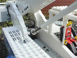
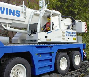
SuperstructureIn building the superstructure I realised how much of the shape of this structure is dictated by function. Placing the counterweight as far back as possible will obviously increase the stabilising moment of the crane, and this is indeed done on the real AC50-1. Why not place it even further back than it is? Often these cranes have to work in confined sites, and having the counterweight protrude too far could limit superstructure slewing, therefore a compromise between counterweight effectiveness and compactness must be reached. While it is possible to have a counterweight capable of moving backwards and forwards under hydraulic control allowing the crane to adapt to different working areas and loads, this is rarely seen in the real world. I have no idea why though, so if anyone has anyone ideas I'd be happy to hear them. Having the counterweight all that way back also allows the boom to be mounted similarly to the rear, maximising the length of boom the crane is capable of carrying whilst moving from site to site without it jutting too far in front of the carrier. As can be seen from the photos and render to the left, the counterweight and boom are suspended on a sloping structure deriving from the rear of the superstructure. I initially had concerns that in Lego form this would not be strong enough, but with a modicum of bracing it prove remarkably stable. These crane designers know a thing or two. I really wanted to accurately capture the appearance of the superstructure, particularly the cab, and while it looks fairly plain the simplicity is only skin deep. Lego do not make slopes of the correct angle to build the side walls of the cab, so I had to take almost vertical slopes and build them in sideways. Doing this seamlessly was fairly awkward, but to make matters worse I had to have some bricks upside down at the front of the cab to allow a seamless fit of the corrugated tubes framing the windscreen. Using bricks upside down, sideways or at odd angles in conjunction with bricks in the normal direction may sounds trivial, but believe me, getting a robust structure in a small space using these methods is guaranteed to twist your brain - in a good way, of course. Well finally, a confession: there is a kludge in this model. The large box with the sloping front on the right hand side of the superstructure does not exist on the real crane - in its place are a few smallish metal boxes, presumably for storing odds and sods. If you examine the render of the superstructure interior you can see that the space created by inclusion of the kludge is certainly not needed, the only item of significance in that area is the remote control receiver which could easily be occupied in a box proportionate to the ones on the real crane. The reason for its existence is to improve the strength and stability of the superstructure attachment to the carrier. In the turntable section I mentioned that the carrier has several flat tiles and rollers placed on it to ensure the smooth rotation of the superstructure on the carrier; on the real crane these are not required as it is possible to make the turntable (or slew ring) strong enough in itself. In reality these turntables are very similar in concept to the thrust bearing described in the boom luffing section, and have integrated rollers to ensure smooth operation. However, on the model the rollers and tiles extend beyond the turntable and it is essential that all parts forward of the centre of rotation of the turntable rest upon those. The cab does this automatically on the left hand side, but if I had stuck religiously to the real AC50-1 the right hand side would have little support in that region and the boom would tend to lean over in this direction. So enter the kludge. I tried to make metal style boxes similar to those on the real crane, but slightly bigger, but they looked like a mistake. On larger cranes, however, the superstructure often extends fully to both sides so I simply took the right hand side of another crane superstructure and fitted in onto this one. I think it works; it looks like it is meant to be there, and unless you know what the real AC50-1 looks like from the right hand side, you wouldn't know otherwise. Thankfully, there seems to be only one photo of this side of the AC50-1, and it isn't on the Internet. Until now, anyway... |
|
|
|
|
|
|
|
|
Click on pictures to
enlarge |
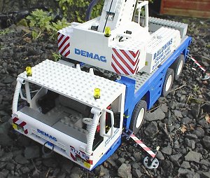
Carrier and ChassisThe previous mobile crane featured on this website was really more of a symbolic representation than a scale model, but for this model I wanted the appearance to be as accurate as possible. I think this has been achieved quite well, although getting the shape correct and still fitting all the mechanical and electrical parts in was perhaps not as easy as I'd like to think! As with the superstructure cab, building the carrier cab required building with the studs facing all sorts of angles as well as some at 1/2 stud offsets, and took many iterations until I was happy with the result. Making the doors and wing mirrors was fun, and required the use of a model knife, file, some small bolts and a drill. The doors are from the Model Team Racing truck, and the original square window had a slope cut in it to resemble to doors on the AC50-1. Next I drilled two holes on each door which then had bolts screwed into them; the end of the bolt was then snipped off to make mounting points for the wing mirror frames. You'll no doubt be glad to hear that the wing mirror frames are made from standard flex tube, although I did put nick in the inside of the corners to help retain their shape. The load bearing portion of the chassis is roughly based around a six stud wide box running most of the length of the vehicle with similar structure firmly attached to this for the outriggers. This H shaped structure ended up surprisingly strong and is very resistant to twisting forces imposed by heavy lifts. One of these days I'd like to rebuild the chassis using the newer studless beams to see if it is possible make it lighter whilst retaining the strength. The whole model weighs 3.6kg so some real benefit would be gained if this worked out. As for the mechanical and electrical complexity of the carrier? A picture paints a thousand words...
|
|
|
|
|
|
|
DAT File DownloadMany DAT files have been used in the creation of this web page, and can be downloaded in a single zip file by clicking here. Some unofficial parts were used in these files, and if you do not already have them they can be obtained from the following locations:
|
References
Credits
|


