This page contains sketchy documentation on various mechanisms I've been
experimenting with, and as such the design of both the mechanisms and page will
be a little rough. This is intentional, however, as spending too much time on
these mechanisms detracts from the point of the exercise - rapid experimentation
and prototyping. For more polished models, please see my main
page.
I designed this combined electric and pneumatic hand controller
unit with on board compressor as a direct replacement for the one featured on
the skid steer loader pages, but with the notion of
it being a "designed for manufacture" production type unit rather than
a prototype for my own use. In order to achieve this the unit had to be:
Anyway, enough specifications... here are the results.
|
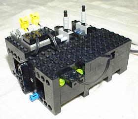
As you would (roughly) see it in use. The compressor can
be switched off by removing the cable attached between the two green
studs. When the cable is attached, it works in "on demand"
mode.
|
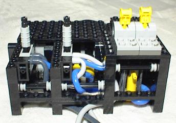
The pneumatic cylinder for the limit switch is on the
bottom right. The two yellow switches provide electrical power to the
model via cables (not shown for clarity); the two grey switches supply
compressed air to the pneumatic sections of the model.
|
Some time ago I received an email from Klaas Meijaard telling me
he had built an air compressor using the grey switch on the small black 9V
battery box as part of the pressure limit switch mechanism. I thought this was a
great idea, giving pneumatic power on demand without having to use one of the
expensive polarity switches found in most compressors, including my own. The
idea was especially appealing since I had accumulated many of these black
battery boxes through purchases of the 8266
kit in sales.
From this, I had the idea of powering not only the compressor
from the battery box, but also the electric parts of the model in mind, my skid
steer loader. Of course, if you use the switch on the battery box as part of
the limit switch to the compressor motor, then you will only be able to supply
electric power to the model when the compressor is running. This is obviously
undesirable, so I powered up a soldering iron and made a few modifications to
the battery box...
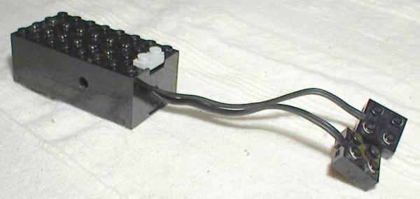
Since the power to the compressor motor comes from the terminals
on the top of the box, and polarity switches were in use for driving the model
in any case, a permanent power supply to the latter was obtained by soldering
the ends of a standard cable directly to the battery terminals inside the box.
Believe it or not, this was surprisingly easy. While making this modification I
also bored a couple of Technic pin sized holes in either side of the box to
allow it to be mounted on the controller without having to brace it from
underneath, thus allowing access to the battery without dismantling the
controller.
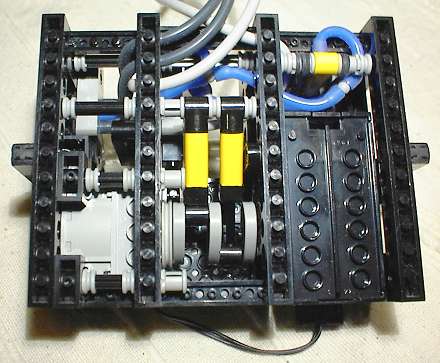
The above picture shows the underside of the controller with a
clear view of most of the components. At the bottom left is the compressor
motor, in the middle are the compressor pumps, the battery box is to the right
and the limit switch is at the top right. Initially the compressor was only a
single pump unit with a higher gearing, but this did not provide adequate
pressure or airflow so 2 pumps acting 180 degrees out of phase were employed
driven directly from the motor. The limit switch, however, is perhaps the
most interesting part of this device...
|
Closed - power flows to the compressor motor
|

Open - the red arrow indicates the battery box switch.
|
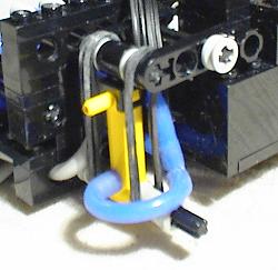
The pressure limit switch mechanism is very simple, with elastic
bands providing the opposing force to the air pressure. When the air pressure is
low, the bands pull the lever made from two 1x4 liftarms down which depresses
the power switch on the battery box and switches on the compressor motor. When
air pressure is high enough to overcome the elastic bands, the lever rises and
the switch (which is spring loaded to return to the off position) rises, cutting
off power to the compressor.
The lever does not have to rise to the height it is at in the
above right picture to switch off the motor - in actuality the movement required
is slight, and I simply moved it this much to emphasise the workings. A good
side effect of this slight movement, as opposed to the large movement required
in limit switches using the polarity switch is the the on/off and off/on cycles
are quicker and more symmetrical, exhibiting less hysteresis.
I have created a DAT file for this controller in MLCAD which can
be downloaded by clicking here. Unfortunately
the version of MLCAD I have does not include the pneumatic cylinder and
compressor pumps so those have been omitted, but it should be obvious from the
photos on this web page where they go. Similarly, I have no idea how to create
pneumatic tubing in MLCAD, so that has also been left out.
3 Section Telescopic Crane Boom - 3/12/00
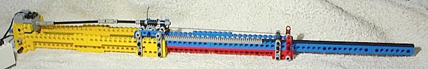
Fully closed (please click on
pictures to zoom in)
|
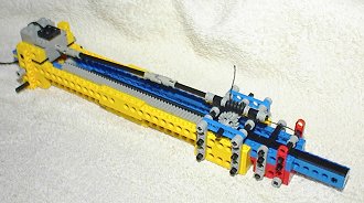
Half open
|
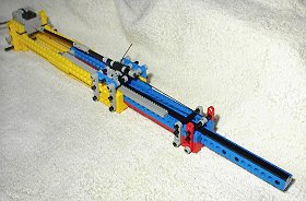
Fully open |
Creating a three section telescopic crane boom from Technic Lego is something
that occurs to many people, however, actually making one is far from
straightforward. Part of the attraction of building this mechanism is that all
the official Lego crane models only have two section booms. While it is
certainly possible to achieve this with a rack and pinion on each moving
section, this entails having a motor on both the bottom boom and the middle boom
- not an ideal solution.
How real telescopic cranes achieved this was a mystery to me until recently, when
I came across a picture showing the workings of a boom in this Acrobat
document from the Liebherr web
site. Basically, only the second section is moved by a hydraulic ram attached to
the first section, with all the other sections being moved simultaneously by a complex system
of pulleys. It is actually very simple when you think about it, but to come up with
this idea in the first place must have required sheer genius. Here is a diagram
showing how it works, in the simpler case of a three section boom; it is
possible to totally conceal the pulley system within the booms, but showing it
this way facilitates understanding.
The red line denotes the cable, red crosses show where it is attached to the
boom, and the red circles represent pulleys. It can be seen from this diagram
that holding one section still and moving any other section relative to it will
produce an equivalent movement in the remaining section. So, to move the third
section in sync with the second, all you need to do is move the second section
relative to the first and it will happen automatically.
My Lego implementation uses a rack and pinion system powered by a single
motor to move the second section relative to the first. What may
not always be obvious at first glance is that the pulley system will actively move the third section when the
boom is telescoping both upwards and downwards - gravity is not required to
retract the boom.
Driven and Steered Vehicle Axle Using Znap Axles - 10/10/00
While the above has been achieved with the 8880 Supercar
including independent suspension, building such a mechanism without the
specialised parts contained in that kit (which only work with the 8880 wheels in
any case) is a very difficult proposition. The difficulty is basically that
standard Technic Lego is just not really setup in terms of strength and scale to
do this, particularly if your vehicle is smaller than Supercar scale.
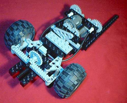
As a somewhat sneaky workaround, I had the idea of using the
flexible axles provided in a Znap kit to power the wheels, which can be fed
directly through the standard steering components, whereas a universal joint
cannot. This is a very unrealistic method, not at all like a real vehicle, but
if it could be made to work I thought there may be some mileage in it. It
actually worked rather well, and while power transmission is not as
theoretically efficient as a standard driven axle system, it seemed to make very
little difference in practice.
The rack and pinion steering is a little too stiff for manual
control, but an electric motor moves it perfectly well. This whole idea is
geared towards a vehicle driven by motors, as opposed to a motor driven by the
vehicle.
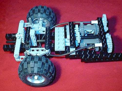
The top differential is the one relevant to the front axle; the
bottom one was intended to be the centre differential in a four wheel drive
setup.
The Znap axles are rubbing against the chassis, but this could be
avoided with better design