Print quality instructions and additional documentation are available from my store and Rebrickable for only $20


Related files: Preview + parts inventory (PDF) | BrickStore parts inventory | Rebrickable Page
Comments from owners of these instructions;
I must say they are SUPERB. The 164 pages are extremely well done and full of background information about the real equipment, and the model. The images are laid out just like official Lego building instructions~ David Luders
The complexity of this model has to be seen (built) to be believed. The quality and clarity of the steps is excellent. I think they're a bargain. A welcome step-up from standard Lego instructions~ Richard Brown
I have never seen the LEGO system pushed so far beyond what I thought were its limits~ Sariel
The instructions are on a par with those created by LEGO, so constructing it should be straightforward enough once you've mustered up the required parts, most of which are commonplace~ Huw Millington admin of Brickset
The instructions themselves look very professional, and the background information makes them even better~ Rijk van Voorst
Read a review of the instructions at Brickset.
Click on pictures to
enlarge |
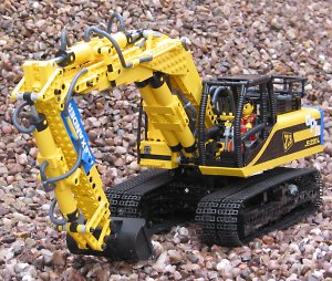
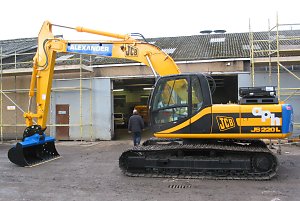
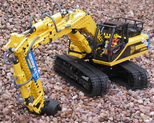
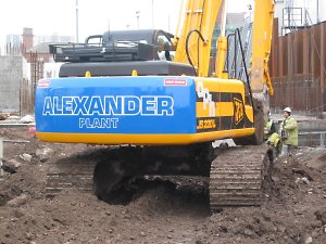
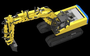
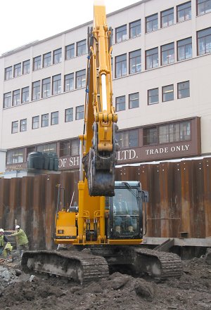
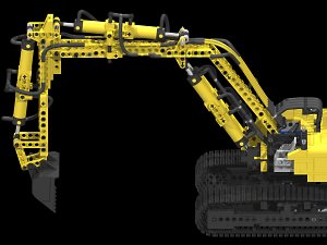
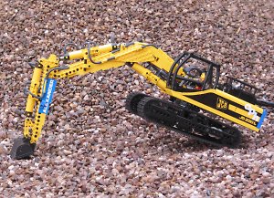
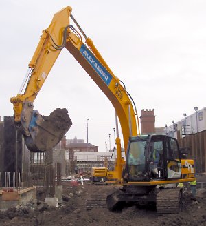
InspirationTracked hydraulic excavators have always been one of my favourite types of construction machinery, and a while back I built a model of the seven ton JCB JS70 excavator documented here. Even while designing this model, however, I was aware of certain limitations, and began forming plans to build an improved version at a later date. The JS70 model worked well enough, but I thought it could be more efficient - there was a lot of friction present in the gears, and consequently the motors had to work very hard for fairly sluggish movements. And while it was a great challenge to model a small excavator to scale, I thought that building one of its larger siblings would present opportunities to overcome these limitations. I had seen the JS220 on the JCB website and at a distance on building sites, and it really appealed to me - at 22 tons it is neither the smallest nor the largest in the JCB range, which I thought would leave plenty room for working functions. Had I chosen a larger excavator to model I suspect the Lego electric motors and pneumatic parts would have had difficulty moving it effectively. At this point it would be usual for me to cite some background information on excavators and digging methods, but I have already done this for the JS70 model, so if this would be of interest please look here. |
|
Click on pictures to
enlarge |
Propulsion
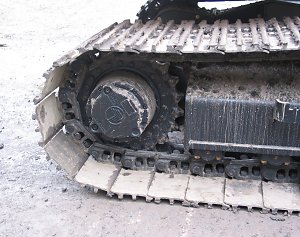
On modern hydraulic excavators, the engine, usually diesel powered, is connected to several pumps that drive hydraulic oil at high pressure to the hydraulic rams and motors used to move all the excavator functions, including the tracks. The diesel engine is relatively small compared to the weight of the machine - the JS220 uses a 128 horsepower unit, not much more than an average car. This low power to weight ratio is typical of hydraulic excavators, and as a result they are very fuel efficient machines when digging in one place. However, the low power to weight ratio also means that they are slow moving, and if required to drive about a lot their efficiency drops off rapidly. For this reason the excavator usually stays in one location while machines designed explicitly for moving about, such as dump trucks, are used to shift the excavated material. As previously discussed with the JS70 model, I wanted to locate all the motors in the excavator superstructure whilst allowing infinite slew of the superstructure relative to the undercarriage. Essentially, a way of routing two independently driven axles through the center of a Technic turntable was required, and such a method was used in the JS70. Unfortunately the JS70 model was too small to allow full implementation of the idea and so infinite slew was not achieved - this required all three motors used for the tracks and slew to be mounted in the superstructure, but only the two track drive motors were located there. Despite this limiting the slew to approximately 180 degrees, the concept was shown to work and provided scope for future development. Thomas Avery went on to build a larger excavator based on the same principle with all three motors in the superstructure, thus obtaining infinite slew. While his developments pushed the Lego state of the art forward, I still saw further room for improvement, and was keen to build these improvements into a new model before someone else did! There are a couple of interesting side effects of this method of propulsion. First of all, assuming the drive motors in the superstructure do not rotate, rotating the superstructure relative to the undercarriage will actually move the tracks. As well as making the excavator behave a bit oddly, this means that slew motor also drives the tracks, leaving less power for its primary purpose.
While not entirely removing this effect from the JS220, I employed a method to reduce its impact. In the JS70 and Thomas Avery's excavator, all of the gear reduction for driving the tracks was in the superstructure before the drive shafts went through the slew ring. With this arrangement, one revolution of the superstructure will rotate the track drive sprocket through one revolution. In the new JS220 model, however, all gear reduction is performed in the undercarriage after the slew ring, and the effect of one rotation of the superstructure is reduced correspondingly. As the total gear reduction is approximately 14:1, the track drive sprocket will move only 1/14 of a revolution for one turn of the superstructure. This is an improvement to the extent that you only notice the effect if you are really looking for it, whereas on the JS70 it was pretty obvious that something strange was happening. Excavator efficiency is also improved, since the amount of wasted effort from the slew motor driving the tracks has also been reduced by a factor of 14. The JS70 had a differential case in the middle of the slew ring acting as the outer concentric drive shaft, whereas Thomas Avery later used transmission gears and driving rings for this purpose, meaning that the gears on either end of the shaft both have 16 teeth, rather than one having 16 and the other 24. As well as using smaller gears, another advantage of his scheme is that it takes up less space vertically, and both of these factors can be used to devise a more compact slew ring design. Unfortunately this method has the disadvantage of having to rotate approximately 90 degrees before the gears fully engage, introducing a lag in the transmission of one track. If gear reduction is done before this point, one track drive sprocket will begin to turn 90 degrees before the other, making the whole excavator rotate before moving off in a straight line. With gear reduction done after this stage, however, the effect is again reduced correspondingly, and with a 14:1 reduction, one track will start to turn only 6.5 degrees before the other, a significant improvement. |
|
|
|
|
|
|
|
Click on pictures to enlarge |
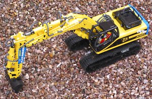
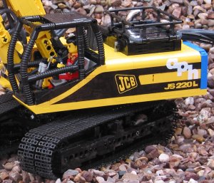
SuperstructureDespite having a similar size of operator's cab to the JS70, the superstructure on the JS220 is far larger and therefore has more usable space for gears, motors and other useful items. Since I was working toward an infinite slew solution this time, with all three motors in the superstructure and less gearing in the drivetrains, it initially appeared that all I had to do was fit one additional motor into all that space - no problem! But then another idea occurred to me; in the JS70 model the battery box was built into the hand controller. This battery box was the small type containing a single 9V battery, which I later discovered could not provide enough power to drive two motors simultaneously, and perhaps not even one motor to its maximum potential. On other models I had used two of those battery boxes in parallel in an attempt to increase their power output, but it was still not as effective as the large battery box containing 6 AA batteries. The obvious solution was to use this larger box, but it was too heavy and unwieldy to be situated in the hand controller. This heaviness could be turned into an advantage, however, if it could be employed as a counterweight at the rear of the superstructure in order to balance the weight of the boom and help prevent the model tipping over. At proper scale, the model was just wide enough to accommodate the battery box, but with the unfortunate side effect that batteries now consumed most of the extra space I thought I had, the effective space leftover being barely more than in the JS70!
The most difficult aspect of fitting all three motors in the superstructure was not the motors themselves, but the drive trains coming from them. Bevel gears on those were required to allow the motors to be mounted so that they would fit completely within the superstructure alongside the battery, but most of this work was contained within the turntable assembly itself. The exception was the slewing motor, for which an ideal solution eluded me for a long time; indeed, on several occasions once I thought I had found a solution, prolonged use of the model revealed flaws in the approach. With the motors and battery box employed as counterweights, very little additional weight was required to balance the digging arm, and a single black Lego weight brick of the type sometimes used in trains was sufficient. In the model, as well as keeping the boom balanced, the counterweight serves to reduce friction on the turntable - if there is too much weight pressing down on one side of the turntable it will not turn as smoothly. |
|
|
|
|
|
|
|
|
|
Click on pictures to enlarge |
Digging Arm
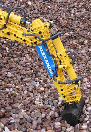
My primary concern when modeling the digging arms of the JS70 and the new JS220 was to make them as functionally correct as possible in terms of dimensions, connections and range of movement. Getting the first two correct is a prerequisite to the last, but will certainly not guarantee it; for example, it would be possible to have the kinematics of the digging arm modeled perfectly, and yet not find a suitable way of attaching the pneumatic cylinders to provide the full range of movement. The first task was to determine the dimensions for the digging arm on the model, and I estimated that the boom would be about three studs wide and the dipper two. However, from previous building experience I knew that making the boom three studs wide would compromise either strength or appearance, and since this model was to have as few compromises as possible, I decided to make the boom four studs wide. This width gives more opportunities to make it stronger while still looking good, and is not so wide as to look unnatural or out of place with respect to the rest of the model. Since the dipper is narrower than the boom in real life and less complex - it doesn't have a bend and therefore can be made with straight beams as structural members - I decided to make it three studs wide. The first difficulty was getting the bend in the boom section at the correct angle. While it would be possible to create the appearance of the bend by stacking plates carefully together, this would not be strong enough. In my experience the best way to approach problems of this type is to build a minimal load bearing structure that will provide all the strength and rigidity required, and then add pieces to make it look correct afterwards. In the JS70 I used two liftarms with single bends to get the angle in the boom, and having not found a better solution for the JS220 I concluded that this would still be the best approach. One problem with this type of liftarm is that the bend is too sharp in comparison to the real excavator boom, which has a far more gradual curve, another is that the angle is slightly too obtuse. Using plates to create a tapered effect on the upper and underside of the lower part of the boom solved both of those problems. Since the load bearing element of the dipper is simply a collection of straight beams fastened together it was relatively easy to conceive, with plates used to create a tapered effect similar to the top of the boom.
Once the rough structural and even rougher cosmetic aspects of the boom and dipper were prepared, the really hard work began, namely that of finding ways of connecting them together so that the full range of movement of the real boom could be recreated. To obtain pneumatic cylinders of a similar scale size two of the Lego cylinders were joined together giving them double their original stroke; In theory it would be possible to use a single cylinder to provide the same range of movement, but its mechanical advantage would be halved, and therefore the maximum force of the components of the digging arm would also be halved. Even with the cylinders doubled up, they were still not precisely the correct size, and this meant their attachment points on the boom and excavator structure had to be different from those in the real JS220 if they were to provide the full range of movement. This was particularly so for the boom cylinders which had a shorter stroke than the real equivalents, and making alternative attachment points on the boom without compromising its strength took some time to figure out. There was another more serious problem with the dipper and bucket cylinders; with the cylinders doubled up the square bases are only connected to each other and are therefore able to spin, and spin they do, causing them to jam on other components. The solution was to put an axle through the cylinder pair and then into guides on either side. These guides are linked together through the supporting structure and therefore move in unison, and as a result the cylinders are prevented from spinning. This is easier seen than explained, so take a look at the photos to the left for clarification!
|
|
|
|
|
|
|
|
|
|
|
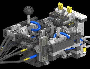
ControllerThe controller for the model uses exactly the same principle as the real JS220 with two joysticks, operated by the left and right hands of the operator, moving the digging arm as shown in the diagram to the left. Having four controls on two joysticks allows the operator to make simultaneous movements without removing his hands from the controls, which would have to be done if four levers were used instead. The Lego joysticks were inspired by Steven Lane who built a couple of prototypes shown here and here. The pneumatic pump is located in the hand controller, and consists of four small pumps configured in a V shape, allowing them to be placed within a compact space. Since there are several pneumatic cylinders driving each function on the model, a lot of air is required to move them, and therefore two motors are used to drive the pump at a high enough speed to provide sufficient airflow. Electric power to drive the compressor comes from the battery box in the excavator. A pressure regulator in the hand controller limits the maximum air pressure in the system by turning off the pump (shown in simplified form in the diagram to the left as a single motor) when the air pressure exceeds a certain value. The hose coming from the small cylinder is attached directly to the pneumatic system, so when the air pressure is high it will tend to push the cylinder out, which in turn moves the electric polarity switch to the off position, removing electric power from the pump. When the pressure in the system becomes low, for example when a pneumatic function of the excavator is operated, the cylinder will retract and switch the pump back on again. Of course, just because there is a controller, doesn't always mean the user is in control...
|
|
|
|
|
|
|
Click on pictures to enlarge |
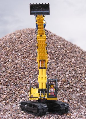
ConclusionsIn many ways the goal of this model was to overcome the shortcomings of the JS70 model, and in this it has succeeded. Many incremental improvements were made to the model after I thought I had finished it, some of which were made to correct flaws in the design only exposed by repeated heavy duty use by the audience at exhibitions! The result of those improvements is that the model is now very robust, and I think the most mechanically sound and smooth operating I have made so far. Don't take my word for it though, look at the videos for the proof of the pudding! If you'd like to build this model yourself, detailed instructions can be downloaded here. |
|
|
Thanks to
References
|